Adjusting Collet Closer - 5C Collet Slipping

dansawyer

Registered
Registered
Joined
Jun 13, 2018
Messages
450
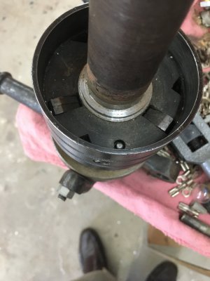
This is a follow on post to a previous post on 5C collet slipping; there may be some duplication, I apologize for that. I would like to focus on the closer mechanism itself. Below is a photo showing the closer in the 'closed' position. My questions are:
First is the mechanism adjusted properly? Are the finger positions approxamately correct?
Second is there an adjustment to increase the 'pull'.
Thanks, Dan


20221007_151112.jpg
 
No it is too far. Those cams should be on the crest of the lock bushing. I guess that is what you would call it.
As for adjustment you might want to loosen the collar that fits the back of your spindle. Then see if it will slide back. If it does that will help you to see what the next step will be.


Cutting oil is my blood.
 
@twhite is correct. Your drawtube is either not threaded onto the collet far enough (or no collet at all) or your drawtube is too long for your lathe.

The user defines the pull on the collet by how far the drawtube is screwed onto the collet.
If the collet's grip on the workpiece is too light, open the closer and thread the drawtube onto the collet a little more.
If you run out of threads, we'll need to look at your collet, how deep the drawtube is threaded and/or how the drawtube length fits your lathe spindle.

JFK is still in business and has graphic for users to fill out so they can make their closer fit your lathe. Have you filled out that sheet?

 
In that picture, the drawtube is pulled out too far.
 
Update:
1. The mechanism that draws the collet is controlled by the 'fingers'. The fingers are on a pin acting as a fulcrum. The long end of the arm is driven by the ramp on the coller. The short end of the arm pushes against adaptor on the end of the spindle. This action draws the collet in.
2. The maximum extent of the arm pushing on the spindle / coller is when the long end of the arm is at its maximum diameter.
3. On the closer in question the mechanism that limits travel is not clear. I am able to adjust it but I am not sure it is correct. I will take another picture and post another thread.
Thank you all for pointing out the fingers should stop on the top. This was the key. Dan

You have explained that very poorly and left me with a false impression of how the device works. My concern is that others might be mislead by your explanation.

"1. The mechanism that draws the collet is controlled by the 'fingers'."
Totally false. The mechanism that draws the collet functions as I explained earlier. The fingers are to engage the slots on the OD of the adaptor secured to the spindle. The purpose is to lock the rotation of the drawtube to the rotation of the spindle.

"2. The maximum extent of the arm pushing on the spindle / coller is when the long end of the arm is at its maximum diameter."
I don't know what any of that means.

"3. On the closer in question the mechanism that limits travel is not clear. I am able to adjust it but I am not sure it is correct. I will take another picture and post another thread."
Did you read reply #3?
We must have different mechanisms. On mine the fingers are levers. When the collet is closed the tapered ring forces the long end of the fingers out. This motion levers other end of the fingers to move to seperate the chrome collet ring from the adaptor ring on the spindle. The creates 'pull' on the collet. The total collet closer distance is less then .1 inch.
On my mechansim there are no slots on the adaptor. The adaptor is a simple piece whick slides over the spindle and is locked on with set screws. It has a clean surface on the other end that the chrome collet ring rides on when not engaged. When the collet closer is closed the short end of the finger arms are forced toward the adaptor ring. This creates the closing force.
 
I got to thinking and remembered about fifteen years ago I had trouble with the closing mechanism moving on the draw tube. After messing with it a few times,
I adjusted it to the right place. Then I welded it in place. I am posting pic of tube
showing where weld is . Looks like a washer in pic but it is a weld that I machined on draw tube.
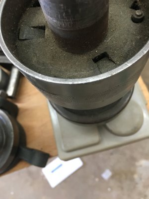
First pic shows mechanism with no weld second shows machined weld. I have 3 Logan lathes and the tube lengths are different.
So maybe problem is mechanism not located in correct location On draw tube.
l am not saying to weld it but maybe adjust it.
jimsehr
 

Attachments

  • 8D8AB088-5771-4B99-85E7-3FC58BD43B19.jpeg
    8D8AB088-5771-4B99-85E7-3FC58BD43B19.jpeg
    197 KB · Views: 5
  • C46C30DF-9BD2-4D8B-9562-277DD15132A8.jpeg
    C46C30DF-9BD2-4D8B-9562-277DD15132A8.jpeg
    192.5 KB · Views: 5
I got to thinking and remembered about fifteen years ago I had trouble with the closing mechanism moving on the draw tube. After messing with it a few times,
I adjusted it to the right place. Then I welded it in place. I am posting pic of tube
showing where weld is . Looks like a washer in pic but it is a weld that I machined on draw tube.
First pic shows mechanism with no weld second shows machined weld. I have 3 Logan lathes and the tube lengths are different.
So maybe problem is mechanism not located in correct location On draw tube.
l am not saying to weld it but maybe adjust it.
jimsehr
This picture looks exactly like mine; I fiddled with mine for hours yesterday. I came to the conclusion that there is a piece missing on the back that limits the travel. I was able to 'test' this by adjusting the threaded rod connector between the cast actuator arm and the lathe body. For now I am simulating a limit by having the cast arm run up against the bearing. (Yes on a scale of 1 to 10 this is close to a 7.)
I am running through potential designs. I have no idea what that part should look like. It should attach firmly to the end of the 'tube' and have an adjustable mechanism to limit the travel.
(I also need a new bearing. Mine is definitely pretty worn.)
There is a stop that limits how far the lever goes back. Move that to shorten stroke Of lever. That should get fingers cam to stop at top of cam Location.

there are 3 bolts holding largest part of mechanism where a knurl pattern is. Under that part is where you adjust length on tube.
 
Back
Top