- Joined
- Nov 18, 2012
- Messages
- 1,352
Hi guys,
A bit of a background. I am a hobby machinist with NO formal machining training. I started in the 70's with a Unimat lathe/mill kit to make RC boat model servos, gear boxes etc. I got a number of accessories for the little machine and did some nice work with it. Then as I moved into restoring old small engines, I got an opportunity to purchase an Atlas 618 from a retired machinist who purchased it new in 1949. And this has been my work horse for the past 4 decades.
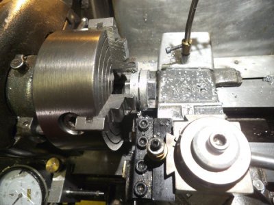
When I retired 7 years ago I decided to repair old mechanical clocks for people. My main go to machine is my Atlas 618 and for milling I am using a circa 1970 Jet 13R bench top drill press made in japan, with a chinesium X-Y table and an old craftsman tilting vise.
I knew that I needed to learn more about machining, so happened upon this forum, after determining that some of the others weren't going to work for me. Since joining here I have learned a lot, and have enjoyed the open discussions in this section on various topics. My first experience was seeing someone make a larger cross feed dial for their lathe and knew right away my Atlas needed that big time. I made one a few years ago and posted in the Atlas section the results of my project. Next I was introduced to LMS and the A2Z QCTP for the Atlas 618. Finally I got rid of the dreaded lantern tool post and things were so much more enjoyable.
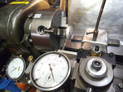
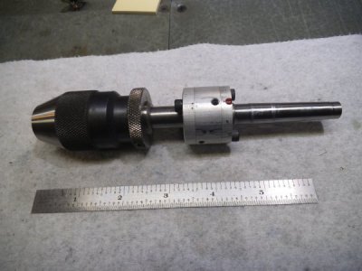
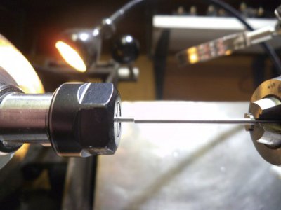
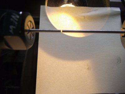
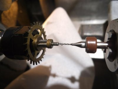
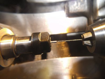
Which brings me to this thread. Frequently in clock repair I have to replace a pivot that is either broken or severely worn on the arbor of a gear. This means that I will have to drill a Ø 0.7mm hole in a Ø 1.5 mm arbor in order to insert a new one. Unfortunately my lathe tail stock chuck is not aligned to that accuracy. Now I see that companies like Sherline offer adjustable tail stock chuck which seems like a tail stock taper with flange mated to a chuck with a flange by a couple of screws with clearance holes so you can bump it around to get alignment and then tighten the screws.
I wanted something that was more controllable in order to adjust the X and Y axis, similar to the jack screws to adjust the X alignment of my tail stock. As I started to progress I realized that I was doing things differently than I had in the past due to information learned here, so thought that this would be a good section to "give back".
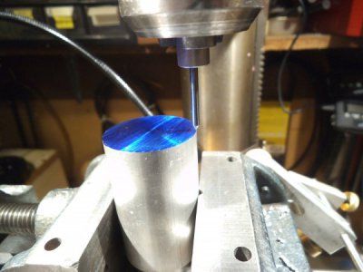
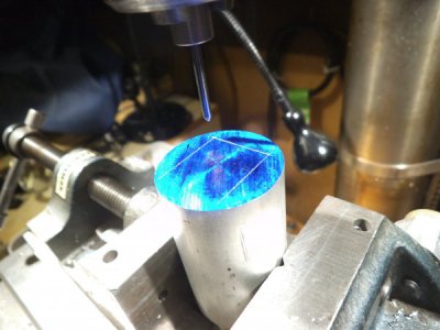
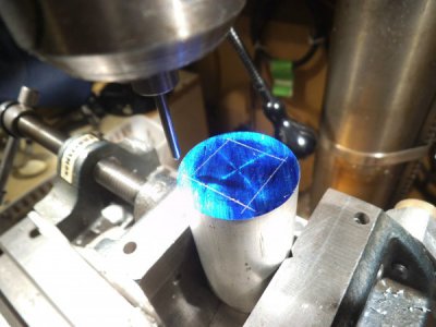
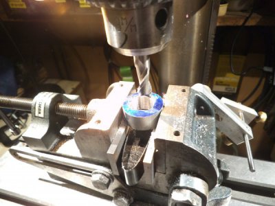
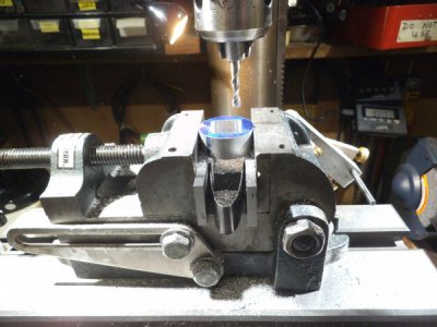
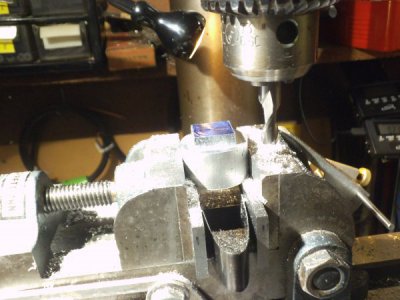
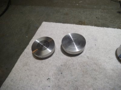
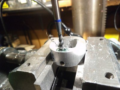
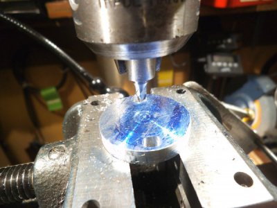
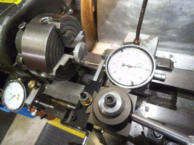
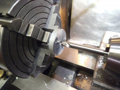
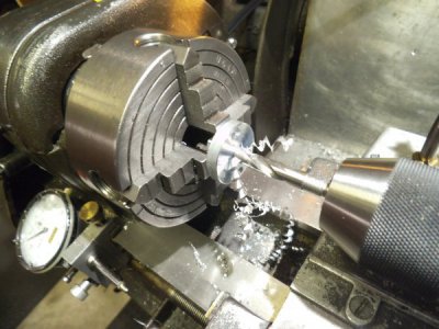
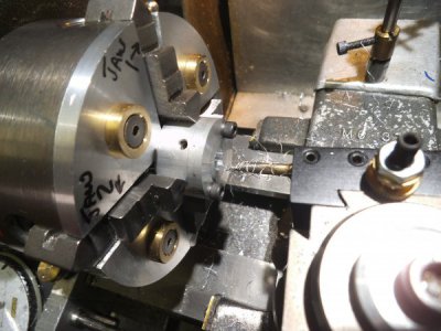
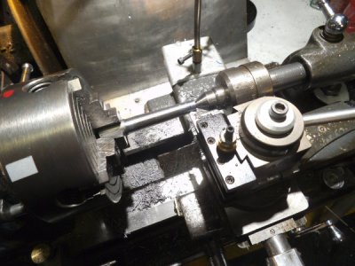
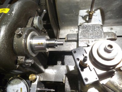
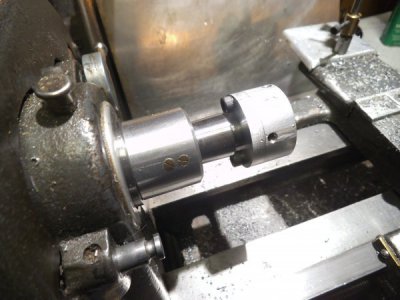
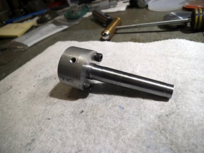
The material that I had on hand is a cut off of Ø 1.25" 6061 aluminum rod x about 2" long, and some Ø 0.5" 12L14, so this is what I am trying to squeeze in. The fasteners are 8-32 set screws and SHCP screws.
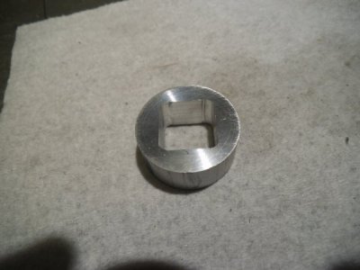
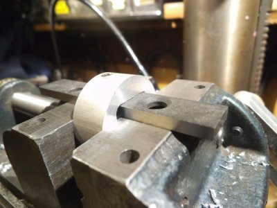
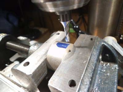
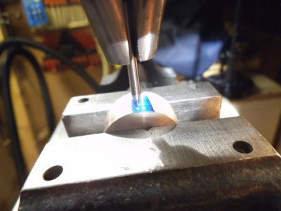
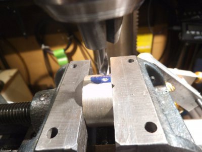
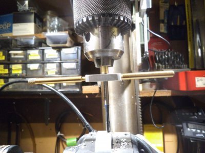
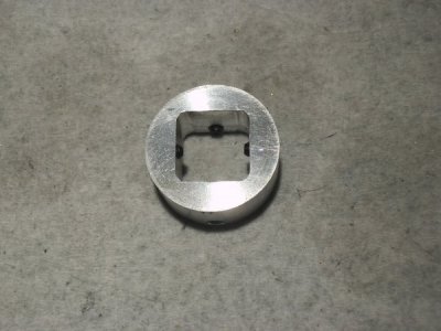
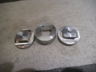
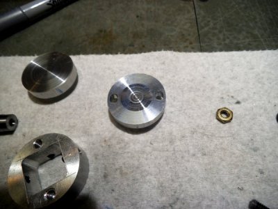
The approach will be to use the two flange method, but with rectangular features on their face that will mate with a coupler with a square centre hole. The idea is to have each flange tuned to slide in the coupler in each of the X and Y axis.
The next post will start the pictures. I hope this is ok to post in this section.
David

