- Joined
- Jul 29, 2014
- Messages
- 2,846
I had an option to add rpm sensing and readout to the last D80 I purchased for $5 additional. That seemed too good to pass up. What I got was a Hall effect sensor and a few magnets...but no other instructions, other than one could use between 1 and 5 magnets and stay within 10mm of the sensor, and how to get the right polarity.
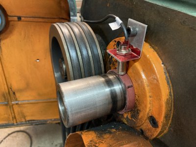
Two of the magnets were very tiny, little discs about 0.060 high and maybe 0.15 in diameter. I thought about a bunch of ways to position the magnets and sensors, and eventually decided to place the magnets around the spindle inside the gear covered area. I had a roughly 2" round of "Rulon", not sure what that is exactly, but a kind of Delrin type material. I cut a ring of it, the ID just being a "press fit" over the spindle, the OD just the height of the little magnets. I drilled two opposite holes in the ring just the diameter of the magnets, slipped the ring over the shaft and poked the magnets into the ring. Then, made another ring with the ID just a few thousandths less than the OD of the inner ring, and slid it over the first ring and the magnets, thus holding the magnets captive. It was straightforward to make an L bracket to hold the sensor and attach it using, opportunistically, an already existing tapped hole, of some originally unknown purpose. The tiny magnets need much closer spacing than 10mm, but it's non-contacting.
Then, configured the DRO for two magnets, and it worked perfectly. The RPM readout starts on the right RPM number and stays extremely stable...surprising me.
This has been a good $5 investment, though the Takisasa has a number of fixed speeds, so I already knew the RPM...just could not resist adding this feature.
This turned out to be a very clean installation. I like it.


