A couple of weeks ago I started a thread about selecting a braking resistor for a CNC mill with a Hitachi WJ200 VFD. Thinking my post would get more exposure here, and therefore help more members, I've created this new post.
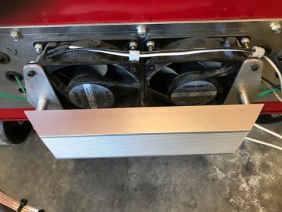
Thanks to the knowledgeable folks on this forum I received the feedback I was looking for and with the new found info in hand I ordered myself a 50 ohm, 500 watt resistor. It came in the mail yesterday so first thing this morning I headed to the shop to install it. Knowing that these things can get hot I decided to mount it on my electronics cabinet cooling fans. Made a couple of brackets and stand-offs and bolted it on. Still need to make a grate or screen to make sure someone, like me, doesn't touch it and get burned.

The wiring was rather simple. Connected one of the resistor leads to the "RB" VFD terminal and the other to the "+" terminal. Next was the parameter changes to make it all work.
F002 = 2.75
F003 = 1.50
A042 = 5
A054 = 60%
A083 = 1
B029 = .5
B090 = 10%
B095 = 02
B097 = 50
B131 = 390
B133 = 1
Then the run test. I ran some simple gcode at 500 rpm that started the spindle CW then stopped and reversed direction. No over current faults so I ran another test at my max speed, 8600 rpm. Here's a video that shows the results. I didn't reverse spindle rotation because I can't envision where I would need to reverse spindle rotation at high speeds. I'm very pleased. Ramps up to speed and decelerates to zero in 1.5 seconds.
For some reason the video is turned 90 degrees and it's distorted a bit. And hopefully the video doesn't take too long to load. I compressed the file from 40 mb down to about 14 mb.
Thanks to the knowledgeable folks on this forum I received the feedback I was looking for and with the new found info in hand I ordered myself a 50 ohm, 500 watt resistor. It came in the mail yesterday so first thing this morning I headed to the shop to install it. Knowing that these things can get hot I decided to mount it on my electronics cabinet cooling fans. Made a couple of brackets and stand-offs and bolted it on. Still need to make a grate or screen to make sure someone, like me, doesn't touch it and get burned.

The wiring was rather simple. Connected one of the resistor leads to the "RB" VFD terminal and the other to the "+" terminal. Next was the parameter changes to make it all work.
F002 = 2.75
F003 = 1.50
A042 = 5
A054 = 60%
A083 = 1
B029 = .5
B090 = 10%
B095 = 02
B097 = 50
B131 = 390
B133 = 1
Then the run test. I ran some simple gcode at 500 rpm that started the spindle CW then stopped and reversed direction. No over current faults so I ran another test at my max speed, 8600 rpm. Here's a video that shows the results. I didn't reverse spindle rotation because I can't envision where I would need to reverse spindle rotation at high speeds. I'm very pleased. Ramps up to speed and decelerates to zero in 1.5 seconds.
For some reason the video is turned 90 degrees and it's distorted a bit. And hopefully the video doesn't take too long to load. I compressed the file from 40 mb down to about 14 mb.
