ACME threading question

mikemm

Registered
Registered
Joined
Apr 23, 2018
Messages
39
I bought a Kennametal LH threading tool holder and an N.3L carbide insert to make new cross feed screw for my Clausing lathe.
I had no issues and it came out great. I also made a matching nut but I used a LH tap for that project.
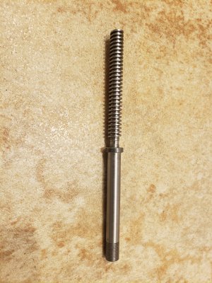
Now I decided to make a new compound screw which is same pitch but smaller diameter and RH thread.
Not thinking about it, I used the same tool and just threaded towards chuck instead of away from chuck to get RH pitch.
I cut to the correct thread depth but the screw binds when inserted into the nut.
I had to cut .0075 deeper into the screw to get sufficient clearance in the nut.
can someone explain if there is an actual geometric difference in a LH insert vs RH insert that would cause the binding?

If I used HSS, there is no LH or RH grind that I am aware of. I would just grind 28 deg and set the tip width in the acme gauge, Correct?

Thanks,

Mike
 
If it fits it fits. Pre made thread form tooling will have different clearance between right hand and left hand thread because of the thread helix. With hand ground tooling there is usually enough side clearance for it to work left or right hand thread. On my Aloris thread tooling the helix is adjustable so it will work with different pitches of threads and even left hand thread without rubbing for lack of slide clearance. High speed tooling is ground with more side clearance than preformed tooling. If you cut it to fit the nut all is good. That's what makes a machinist better than the machine.
 
This speaks to a basic question I have. ACME thread cutting is something I have to get right quite soon, and my congratulations to @mikemm for making his Clausing proud!

For most threading, the helix angle is near enough vertical that we just set the tool straight up and go.
When it comes to ACME threads used for lead screws, the 29° included angle in the tool is universal, and the size of the thread is simply about how deep you cut.

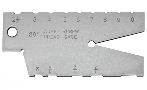
I suppose if the tool is a carbide insert, you need the right size. Those using a thread gauge for making their own would grind on the tool pointy end until it is just wide enough to fit into the appropriate little width slot on the gauge.
29-Degrees-Acme-Screw-Thread-Gage-1F.jpg
If the nut was binding, then it might have been from one of several causes, but mainly, would have been from the width at the pressure face on the thread being too wide for the same place in the nut, or from the peaks of the thread hitting the depths of the tapping bottoms. Cutting deeper solves one cause while making the other worse (I think).

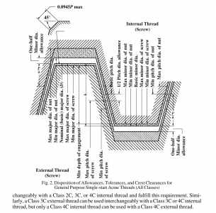
The fragment from the famous handbook shows a nightmare of overlapping tolerance zones, and much fine work went into all the tables. I have to admire the skill of those who would cut threads so big that they cannot just plunge, but instead have to go down from one side, and progressively cut the profile across to the other, and still end up with a great finish.
ACME-Tol.png
The question:
If the helix angle is significant, is the tool always dead straight square, regardless?
I can't really imagine "rotated" cutters tilted to "fit in"the sloping helix, and I imagine a left-had helix would require a tilt "the other way".
My apologies if it's a silly question. I happen to be one with zero experience of ACME thread cutting.

I agree with @Nutfarmer with the "If it fits - it fits" philosopy.
My first adventure with ACME was in avoiding all the machining by making a compound leadscrew nut from bronze-loaded JBWeld potted around the screw. It worked, but the lesson on the way was that it truly needed the clearances! The first try broke as soon as I tried making the screw travel any place past the spot it had been set. The second try was also damn tight, but I progressively lapped it a little until it would travel all the way to the (unworn) end. It was interesting, but not the best I would generally try to do.

I will yet be cutting ACME threads for existing stuff, but at least some of the thoughts are going in the bought-in ballscrew direction if I ever want to play with CNC.
 
Just a general suggestion. I was always taught to make the nut first and use it for a gage for making the screw. This is especially helpful on long screws when not using a steady follower and the threads may be larger in the center of the screw as the forces push the screw away from the threading tool while machining.

Ted
 
Did you check the tool with a gauge (like the picture above)?
 
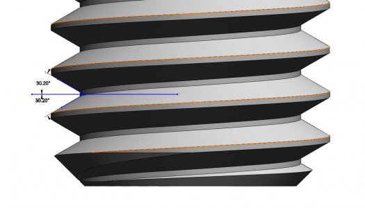
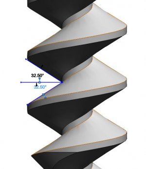
The actual thread form is dependent on the diameter of the thread. A smaller diameter has a sharper helix angle with respect to the axis of the thread. This is generally ignored when cutting a thread but becomes increasingly important as the diameter decreases.

A true thread profile should follow the helix but single point thread introduces the thread form at right angle to the thread centerline. Here is an example of an M5-.8 thread and an exaggerated M1.5-.8 thread. The threads were generated by sweeping the 60º thread form along the helix. Notice that while the apparent angle is close to 60º for the M5 thread, the exaggerated thread is 4º larger. Cutting with a 60º form tool will result in the actual flank angles being about 28º per side.

M5 .8.JPGM1.5 .8.JPG
 
Just a little note, the metric equivalent ( German Trapez thread) of the Acme thread is 30 degree included angle.
 
Thank you all for your replies, now I have a better understanding of the relationship between the form tool and helix direction and why the extra depth was needed to achieve the side clearance. I looked closely at the carbide insert and I see it is not quite symmetrical and is skewed slightly off axis. (Direction of helix I assume)

Just a few side notes based on comments and suggestions. I do make the nut first and use it as the reference size as I can't adjust the cutting depth of the tap and that is a fixed dimension. I am careful of thread height and relief depth and mic those dimensions before making the thread. I also take many spring cuts for uniform thread width and take a finish OD cut to remove the burrs created on the OD of the acme portion. This is how I know the binding is on the pressure surface only.
The only thing you can check a carbide insert in the acme gauge is the tip width which was a hair undersize at 10. That is irrelevant because as I stated in my original post, the cross-feed screw came out perfect at the correct thread depth.
The diameter of the compound screw is smaller than the cross-feed screw, 3/8-10 vs 5/8-10, so did smaller diameter made the helix angle more sensitive to clearance thus requiring the deeper cut to compensate for the directionality of the carbide tool?

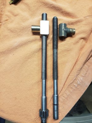
You can see in the picture that I ended up cutting deeper into the relief area than the original relief depth. I am also including a picture of the cross-feed screw & nut.20211113_002637.jpg
I guess the important thing here is it fits

20211112_122550.jpg
 
Looks like there may have been a little backlash in the middle of that old one.
The replacement looks really nice.
I need to make the same parts for mine.
Joe
 
Have not done ACME threads, but when using lay down carbide inserts there are separate inserts for left/right hand threads as well as internal/external. In addition there is a anvil under the insert which sets the insert angle and needs to be changed for the thread type, pitch and also the diameter of the work.
 

Attachments

  • Carmex Thread Turning Inserts Technical Section.pdf
    1.2 MB · Views: 8
Back
Top