- Joined
- Feb 18, 2016
- Messages
- 451
This took me much more than a day. In part because I'm only just starting out and had to figure out which tools to use and how to go about each stage of the process. So for me this was quite the journey. I took a lot of photos so grab your favorite beverage and sit back and hopefully enjoy the journey.
Prologue: I have a combo lathe/mill. It came with a 4" 3-jaw chuck. I just bought a 6" 4-jaw raw chuck for it and this is the story of how I custom made a backing plate for it. I also modified my lathe in the process. The original spindle only had through-holes in it and the original chuck was bolted on from the back side of the spindle. That has been very frustrating for me because those bolts were really hard to get at. So when I made this new backing plate I also drilled and tapped the original spindle so I can bolt everything on from the front. So that job is included in the following journey.
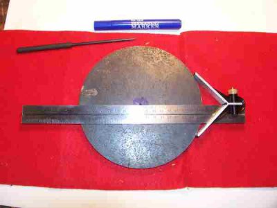
I began with a piece of 6" x 1/2" round steel plate that I bought on Ebay. The plate had been plasma cut so it wasn't perfectly round. I started by finding the center of the plate with a simple ruler center-finder and drilled a 1/8 hole for the new center. This would be my reference for the rest of the project.
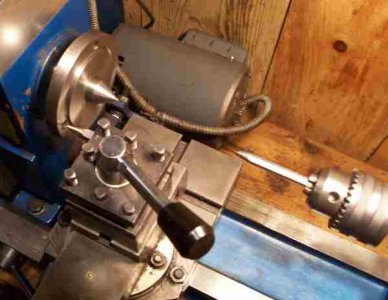
I then set the lathe up with a couple centers so I could stick this plate between the centers and spin it by hand. I also put a center punch in the tool holder to use as a scribe. The idea is to set the center punch up to the center of the hole pattern on the lathe spindle and then transfer that circle to the backing plate disk.
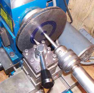
I then put the backing plate between the centers and blued it so I could scribe the lines onto the plate. I did this for both the bolt pattern and for the chuck reference lip.
I did this all by hand without turning the lathe on. This was just my way to transfer these measurements without having to deal with actually trying to measure them.
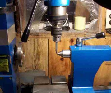
I then set up the milling head so that it was perfectly centered with the lathe center. And locked it down. Strangely this milling head doesn't have any degree markings so I just put center in the mill and line it up with the tailstock center.
I then mounted my dividing head on the milling table. With the plate perfectly centered on the dividing head. I had to do some work to get that plate perfectly centered on the dividing head but I didn't take any photos of that process. But the following photo shows the dividing head being lined up with the center of the mill quill.
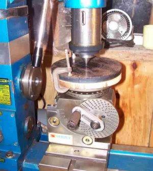
I then put a center drill in the milling head and used the z-axis of the lathe carriage to move the center drill over to the bolt pattern line I had previously marked. Then I used the dividing head to center drill 3 equally spaced holes in the plate. The assumption being that the three holes in the lathe spindle plate are also properly spaced. And fortunately it turns out that they were.
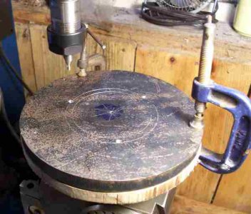
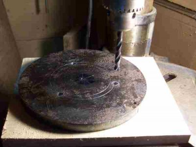
I then took the plate off the mill and over to the drill press to finishing drilling out the holes for an M8 tap. I couldn't do this on the mill because there wasn't enough room to get a drill bit in the milling head. The dividing head was too tall. But it wasn't a problem because the center drilled holes had already set the pattern.
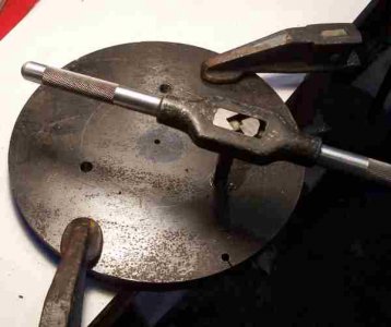
Finally I tapped the three holes.
And now I was finally at a point where I could mount this on the lathe spindle. It's mounted here using the bolts that bolt on from the back.
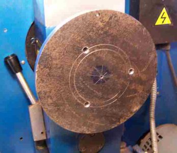
For me this was a major job just to get to this point. But it worked well. I now have the plate mounted in the lathe and was able to turn down the outside diameter to true it up.
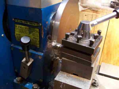
In the photo below notice that the back side of the plate is not flush with the lathe spindle. This is because there is a chuck reference lip in the middle of the spindle. So I will need to cut that reference next.
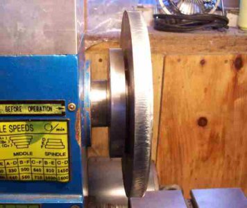
And so I cut the chuck resister relief hole. I was careful to measure this as close as I could. I actually used the original chuck as a reference, and I fortunately got a perfect fit the first try. This will actually be the back of the backing plate when we're done here.
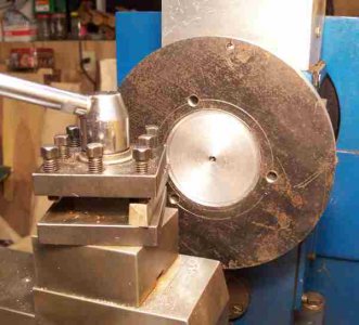
Finally I faced off the backing plate just to clean it up.
Now we can turn it around and put it on the right way so the register relief fits over the resister lip on the lathe spindle.
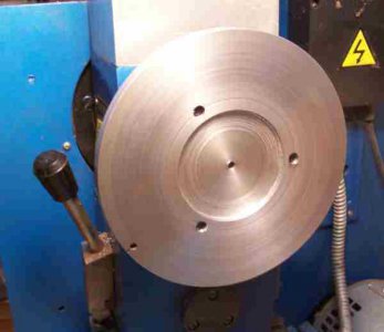
But first I decided to fit this lathe spindle so I can bolt things on from the front.
So back to the dividing head and milling machine. I could have done this the first time but didn't think of it.
This time I just drilled through holes in the backing plate. Again using the dividing head to space them evenly.
And thanks to my new ER-20 collet system for the milling head I was able to hold a drill bit with enough room to drill the holes.
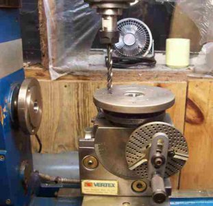
I then needed to have a register lip for the 4-jaw chuck. But I didn't want to turn the 1/2" plate down any thinner. So instead of facing it off to create the lip I found a piece of 1/4" thick aluminum plate and bolted that onto the backing plate. That process was a small journey in and of itself which I didn't take pictures of.
But here's the plate with the aluminum register lip mounted on it.
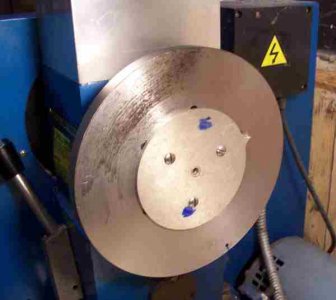
I then turned that aluminum plate down to fit the 4-jaw chuck register relief. I just turned it down right there on the backing plate.
After I got that register finished I put the plate back on the mill again and used an end mill to countersink the bolts that will mount the plate to the lathe spindle. They need to be flush with the backing plate because the chuck will also mount up flush against the backing plate.
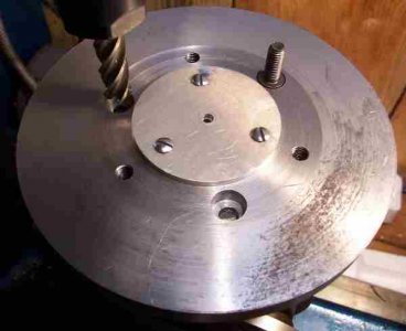
However, before I can bolt the backing plate to the lathe spindle from the front I needed to drill and tap holes in the spindle itself.
So here I have the backing plate bolted on the spindle again from the back just to hold it in place.
Then I drilled through the holes in the backing plate into the lathe spindle. This way I know they'll be perfectly lined up.
I hardly ever actually measure anything if I don't need to.
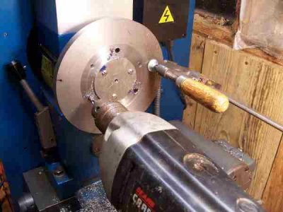
With the holes drilled in the hardened spindle (yes it was some tough drilling), I had to resharpen the bit quite a few times to get through it but I made it.
And then came the tapping of the holes in the hardened lathe spindle.
It took me 3 hours to tap them. An hour a hole. That's because I could only tap a few thousandths at a time. I had to keep backing the tap out and clean out the hole to tap another few thousandths. But I made it. I got all three holes tapped without breaking the tap. But it took a lot of patience.
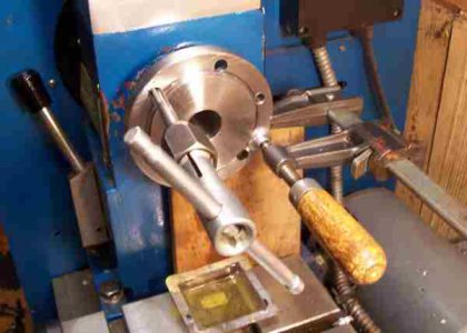
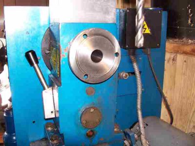
Finally! I can now mount things on the spindle from the FRONT!
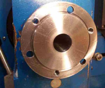
And so I did! Isn't that pretty? I really feel good about having done that. No more messing around with trying to bolt things on from the back.
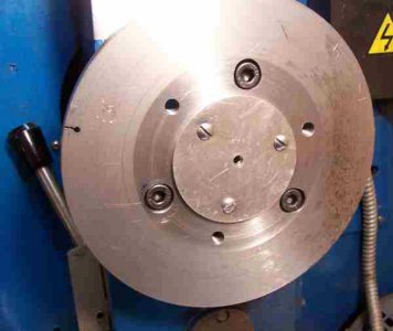
Ok, at this point I had to order some larger drills and taps for the chuck bolts. There are four bolts on the 4-jaw chuck and they came dangerously close to the holes I already had in this backing plate. But fortunately everything just barely cleared. I didn't take photos of that process. But I had to drill and tap the four holes for the chuck bolts.
And now I have a 6" 4-jaw chuck on my lathe. Yippee!
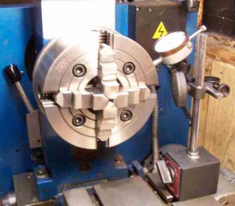
This was one whale of a journey for me. It actually took me over a week to do this. Of course I wasn't working on it full time.
You can see the indicator in the photo above. This chuck runs out exactly 1 thou on the outside surface of the chuck. Not bad. Especially since it's a 4-jaw independent.
I also ran the lathe and it spins very nicely. I took it up to the max speed of my lathe which is 1600 RPM and it was still smooth as silk with no vibrations. So I consider this to be a success.
It took me a lot longer than I originally thought it would take. But then again, part of it was tapping out the lathe spindle so I can bolt things on from the front. I'll be forever glad I did that though.
Thanks for reading, and I hope you enjoyed the journey.
And yes, I know it could have been done more efficiently with better planning. But I'm still learning.
Prologue: I have a combo lathe/mill. It came with a 4" 3-jaw chuck. I just bought a 6" 4-jaw raw chuck for it and this is the story of how I custom made a backing plate for it. I also modified my lathe in the process. The original spindle only had through-holes in it and the original chuck was bolted on from the back side of the spindle. That has been very frustrating for me because those bolts were really hard to get at. So when I made this new backing plate I also drilled and tapped the original spindle so I can bolt everything on from the front. So that job is included in the following journey.
I began with a piece of 6" x 1/2" round steel plate that I bought on Ebay. The plate had been plasma cut so it wasn't perfectly round. I started by finding the center of the plate with a simple ruler center-finder and drilled a 1/8 hole for the new center. This would be my reference for the rest of the project.

I then set the lathe up with a couple centers so I could stick this plate between the centers and spin it by hand. I also put a center punch in the tool holder to use as a scribe. The idea is to set the center punch up to the center of the hole pattern on the lathe spindle and then transfer that circle to the backing plate disk.

I then put the backing plate between the centers and blued it so I could scribe the lines onto the plate. I did this for both the bolt pattern and for the chuck reference lip.
I did this all by hand without turning the lathe on. This was just my way to transfer these measurements without having to deal with actually trying to measure them.

I then set up the milling head so that it was perfectly centered with the lathe center. And locked it down. Strangely this milling head doesn't have any degree markings so I just put center in the mill and line it up with the tailstock center.

I then mounted my dividing head on the milling table. With the plate perfectly centered on the dividing head. I had to do some work to get that plate perfectly centered on the dividing head but I didn't take any photos of that process. But the following photo shows the dividing head being lined up with the center of the mill quill.

I then put a center drill in the milling head and used the z-axis of the lathe carriage to move the center drill over to the bolt pattern line I had previously marked. Then I used the dividing head to center drill 3 equally spaced holes in the plate. The assumption being that the three holes in the lathe spindle plate are also properly spaced.
 And fortunately it turns out that they were.
I then took the plate off the mill and over to the drill press to finishing drilling out the holes for an M8 tap. I couldn't do this on the mill because there wasn't enough room to get a drill bit in the milling head. The dividing head was too tall. But it wasn't a problem because the center drilled holes had already set the pattern.

Finally I tapped the three holes.

And now I was finally at a point where I could mount this on the lathe spindle. It's mounted here using the bolts that bolt on from the back.

For me this was a major job just to get to this point. But it worked well. I now have the plate mounted in the lathe and was able to turn down the outside diameter to true it up.

In the photo below notice that the back side of the plate is not flush with the lathe spindle. This is because there is a chuck reference lip in the middle of the spindle. So I will need to cut that reference next.

And so I cut the chuck resister relief hole. I was careful to measure this as close as I could. I actually used the original chuck as a reference, and I fortunately got a perfect fit the first try. This will actually be the back of the backing plate when we're done here.

Finally I faced off the backing plate just to clean it up.
Now we can turn it around and put it on the right way so the register relief fits over the resister lip on the lathe spindle.

But first I decided to fit this lathe spindle so I can bolt things on from the front.
So back to the dividing head and milling machine. I could have done this the first time but didn't think of it.
This time I just drilled through holes in the backing plate. Again using the dividing head to space them evenly.
And thanks to my new ER-20 collet system for the milling head I was able to hold a drill bit with enough room to drill the holes.

I then needed to have a register lip for the 4-jaw chuck. But I didn't want to turn the 1/2" plate down any thinner. So instead of facing it off to create the lip I found a piece of 1/4" thick aluminum plate and bolted that onto the backing plate. That process was a small journey in and of itself which I didn't take pictures of.
But here's the plate with the aluminum register lip mounted on it.

I then turned that aluminum plate down to fit the 4-jaw chuck register relief. I just turned it down right there on the backing plate.
After I got that register finished I put the plate back on the mill again and used an end mill to countersink the bolts that will mount the plate to the lathe spindle. They need to be flush with the backing plate because the chuck will also mount up flush against the backing plate.

However, before I can bolt the backing plate to the lathe spindle from the front I needed to drill and tap holes in the spindle itself.
So here I have the backing plate bolted on the spindle again from the back just to hold it in place.
Then I drilled through the holes in the backing plate into the lathe spindle. This way I know they'll be perfectly lined up.
I hardly ever actually measure anything if I don't need to.


With the holes drilled in the hardened spindle (yes it was some tough drilling), I had to resharpen the bit quite a few times to get through it but I made it.
And then came the tapping of the holes in the hardened lathe spindle.
It took me 3 hours to tap them. An hour a hole. That's because I could only tap a few thousandths at a time. I had to keep backing the tap out and clean out the hole to tap another few thousandths. But I made it. I got all three holes tapped without breaking the tap. But it took a lot of patience.

Finally! I can now mount things on the spindle from the FRONT!

And so I did! Isn't that pretty? I really feel good about having done that. No more messing around with trying to bolt things on from the back.

Ok, at this point I had to order some larger drills and taps for the chuck bolts. There are four bolts on the 4-jaw chuck and they came dangerously close to the holes I already had in this backing plate. But fortunately everything just barely cleared. I didn't take photos of that process. But I had to drill and tap the four holes for the chuck bolts.
And now I have a 6" 4-jaw chuck on my lathe. Yippee!

This was one whale of a journey for me. It actually took me over a week to do this. Of course I wasn't working on it full time.
You can see the indicator in the photo above. This chuck runs out exactly 1 thou on the outside surface of the chuck. Not bad. Especially since it's a 4-jaw independent.
I also ran the lathe and it spins very nicely. I took it up to the max speed of my lathe which is 1600 RPM and it was still smooth as silk with no vibrations. So I consider this to be a success.
It took me a lot longer than I originally thought it would take. But then again, part of it was tapping out the lathe spindle so I can bolt things on from the front. I'll be forever glad I did that though.

Thanks for reading, and I hope you enjoyed the journey.
And yes, I know it could have been done more efficiently with better planning. But I'm still learning.


