- Joined
- May 17, 2012
- Messages
- 105
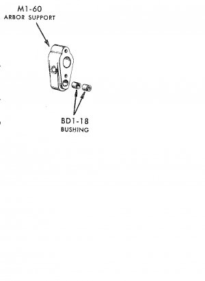
Well, I'm now working on the drawing for the last remaining missing critical part on my Craftsman Horizontal mill. I did find a metric drawing on line, and I'm working on turning it into a drawing of an M1-60.
Looking at some pictures captured from Ebay, I can see I already have a problem. When I try to scale features off the pictures, I estimate the thickness of the part as 1.5 inches. Based on the metric drawing, I bought 1" stock. If this is done in steel, perhaps that's thick enough.
I know the size of the overarm (1.5") and can estimate the width of the top of the support at 2". The bolt heads look to be 1/2", or a 5/16 bolt for the overarm support bracket. The distance between the center of the overarm and the center of the bearing is 2.875" (but that will be bored in place). The thinnest standard bearings are 5/8 id, 3/4 OD. This also appears to be the diameter of the lug for the arbor support on the top of the bracket. Some of the big decimals come from the 5/16 bolt assumption.
Any comments on the dimensions would be appreciated. I don't have the drawbolt or oiling channel drawn in yet. Dimensions of the diameter of the pinch segments, and their protrusion into the overarm bar are hard for me to estimate. I suppose I could use the same dimensions as the ones on the mill head... thought of that as I was typing.
A second issue is the bearing material. I really don't have any idea of the magnitude of the cutting forces. The metric drawing shows a bronze bearing with an external oil groove and holes. Oillite is readily available, but I don't know if that has adequate bearing capability, nor do I know the proper method to externally oil an oillite . I have heard that if you try to machine the bearing surface, you ruin the properties of the bearing.

