I have a 9A lathe with the later plunger-type reverse tumbler assembly.
When the stud gear is mounted it does NOT line up with the idler.
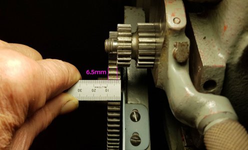
This has been a great mystery to me for the past 25 years. However, yesterday I pulled the gear train apart for "regular" maintenance and, after comparing my reverse shaft with some advertized eBay parts, I came to the conclusion that I have the wrong type of reverse shaft:
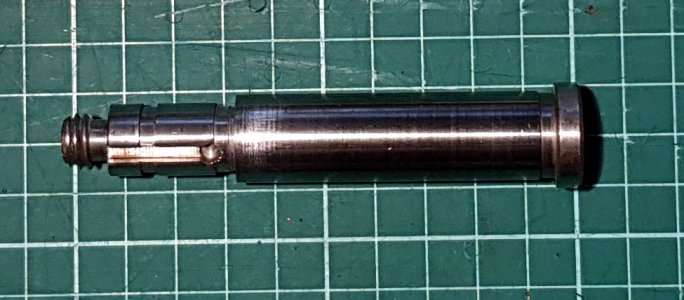
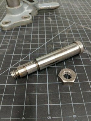
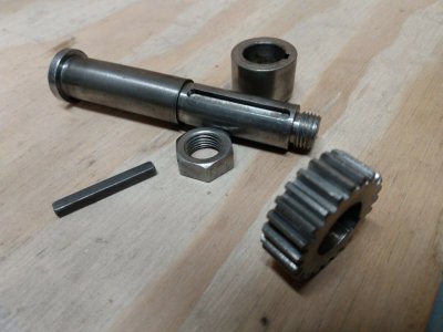
........................ my part ..................................................................older bolt-type shaft..............................newer, plunger-type shaft (?)
I assume that the newer plunger-style shaft must be about 3/8" longer than the previous type to suit the new bracket which was longer - see comparison of the two brackets below:
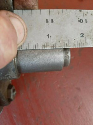
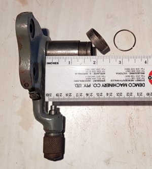
old bracket 1 3/8" long ................................................... new bracket 1 3/4" long
The simplest way for me to make my stud gear line up with the idler would be to chop the extra length off the new-type bracket.
HOWEVER ... I know that the South Bend Engineer who designed the later plunger assembly bracket greatly increased the cost and complexity of the assembly by adding a special spring steel band and a circlip, which required lengthening the casting, and then more turning and grooving. Clearly there must have been a purpose behind this seeming madness.
The spring band (PT2585K2) is labelled "lock bushing", but it's hard to see how it would lock anything since it is at least 0.001" smaller than the bracket OD .
The circlip must serve to prevent the spring band from sliding off, but WHAT IS THE IMPORTANT PURPOSE OF THE SPRING BAND ?
Can anyone explain ? or even guess ?
When the stud gear is mounted it does NOT line up with the idler.

This has been a great mystery to me for the past 25 years. However, yesterday I pulled the gear train apart for "regular" maintenance and, after comparing my reverse shaft with some advertized eBay parts, I came to the conclusion that I have the wrong type of reverse shaft:


........................ my part ..................................................................older bolt-type shaft..............................newer, plunger-type shaft (?)
I assume that the newer plunger-style shaft must be about 3/8" longer than the previous type to suit the new bracket which was longer - see comparison of the two brackets below:


old bracket 1 3/8" long ................................................... new bracket 1 3/4" long
The simplest way for me to make my stud gear line up with the idler would be to chop the extra length off the new-type bracket.
HOWEVER ... I know that the South Bend Engineer who designed the later plunger assembly bracket greatly increased the cost and complexity of the assembly by adding a special spring steel band and a circlip, which required lengthening the casting, and then more turning and grooving. Clearly there must have been a purpose behind this seeming madness.
The spring band (PT2585K2) is labelled "lock bushing", but it's hard to see how it would lock anything since it is at least 0.001" smaller than the bracket OD .
The circlip must serve to prevent the spring band from sliding off, but WHAT IS THE IMPORTANT PURPOSE OF THE SPRING BAND ?
Can anyone explain ? or even guess ?
Last edited:
