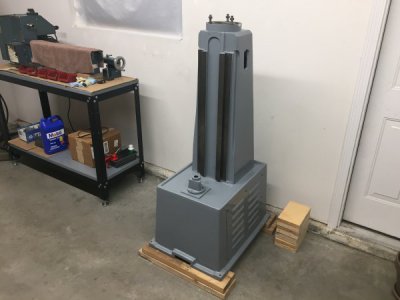
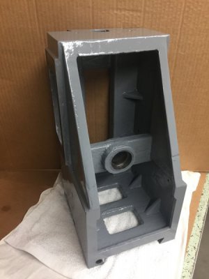
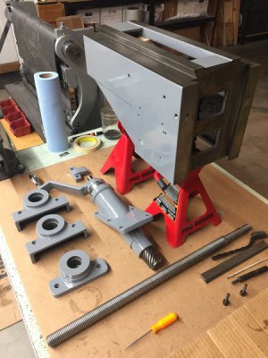
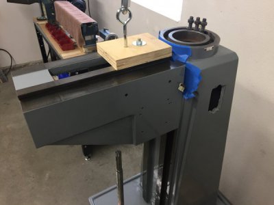
8x30 Milling Machine Restoration

Radials

Registered
Registered
Joined
Feb 7, 2018
Messages
171
After over a year of this project the finish line is slowly creeping into sight and I've decided it's time to put together my pictures and notes from the rebuild of this milling machine to post out to the forum. Admittedly a rebuild like this wouldn't take nearly this long had I been able to focus full time on it but life only allows so much some times. In any case I'm pleased with how it has developed, and I'll now attempt to catch this posting up as quickly as possible to where things actually are in the rebuild process.

Let's go back to the beginning...

I had been on the lookout for a milling machine for a garage machine shop for a while. A knee style mill was most desirable to me and I had narrowed my search down to the Taiwanese 8x30 mill. Grizzly seemed to be the only company still importing these but paying over $4K for just the mill wasn't going to happen which put me into the used market. After about 5 months of looking one showed up on eBay that seemed like a good candidate. It was listed by a machinery seller in the greater LA area so shipping up to Oregon wouldn't be too bad. The machine was listed as a 20 to 30 year old house branded floor model that has never been used. Essentially new, but in need of a rebuild from sitting so long. I made them an offer which was declined, so I made a higher one which was my limit and they also declined that. A month and a half later the machine is still listed so I made yet another offer just a shade above my first low offer and they accepted. On the truck it went up here to Oregon.
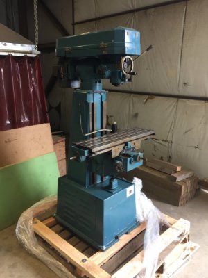
IMG_4593.JPG

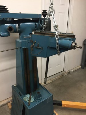
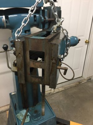
Here's the mill right after I pulled it off the truck. It certainly looked like its sat around for a long time but with no signs of ever being used. They stated that the handles were removed at one point and sold to another customer so there was an obviously long period of time that the machine wasn't even being cranked based on the oil staining marks from where the saddle and knee have been situated.
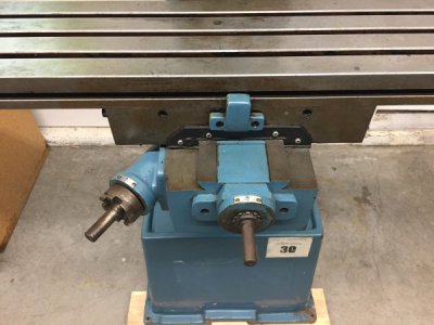
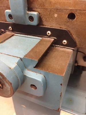
IMG_4605.JPG
IMG_4607.JPGIMG_4608.JPG

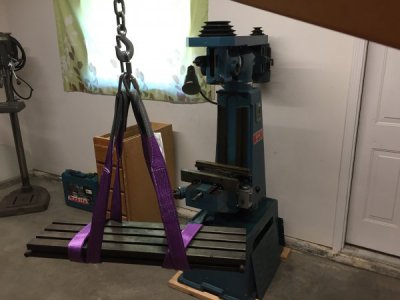
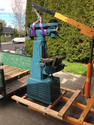
A coworker helped me get the machine home and unloaded. The engine hoist (crucial!!) worked great but was at it's travel limits lifting it off the trailer so some scooting and swinging was needed to get it all the way.
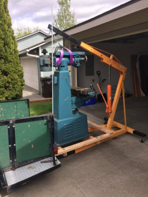
IMG_4599.JPGIMG_4600.JPG

After getting the mill on the floor the route forward was to fully disassemble it for a thorough cleaning and paint job after fixing all the chips in the fairing compound.
 
An engine hoist in a small shop is a necessity in my opinion. I have moved this machine 3 or 4 times along with lifting all the heavy sub components and it's still proven to be the best money I've spent in the shop thus far. It's also what makes doing all this solo even possible.

The teardown was pretty straight forward. I downloaded the Grizzly G0730 manual for a parts and assembly reference. The Grizzly model is identical to this mill. It's since been discontinued however but the G0731 is still available except comes with a factory x-axis power feed.

IMG_4752.JPG
IMG_4754.JPG
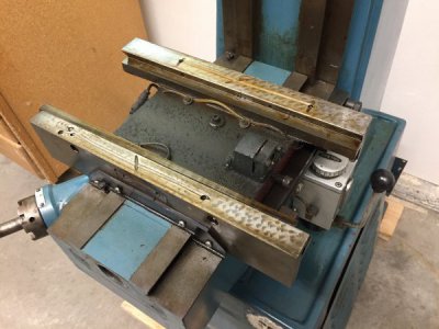
All the oil on the machine had turned into a varnish. Nothing slid but the sliding surfaces looked great. I used lots of penetrating oil to get things
to start moving.

IMG_4767.JPG
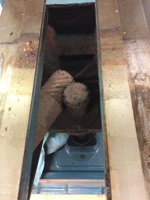
Thick layer of fuzz dust on the knee bevel gears.

IMG_4819.JPG

IMG_4820.JPGIMG_4821.JPG
Thick chunk of (old grease?) blocking off one of the knee oil feeds. I'm not even sure how this would have gotten in there but good to find.

IMG_4626.JPG
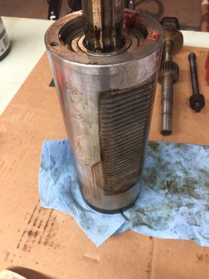
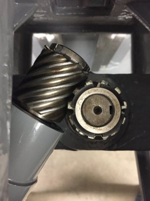
The spindle was seized and the grease on top was clumpy. In fact all the grease in the machine is clumpy. While the upper bearing (visible in picture) was trash the spindle bearings did clean up beautifully. Had I put power to the machine right from the get go they would have been trashed as well. Along with the upper head bearings which also cleaned up great.
 
During the course of the tear down I came across a number of disappointments that are probably to be expected in the import machine arena. The ones I could do something about I would.

IMG_4948.JPG
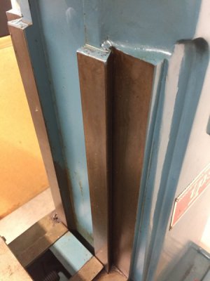
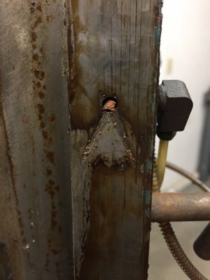
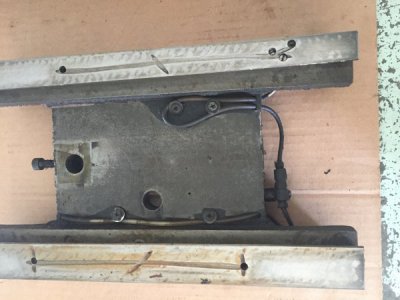
Take note of the two set screws on the top surface of the x-axis saddle dovetail. That's where the guy at the factory missed the drill hole to the oil passage below twice and plugged the holes with the screws. Third times a charm....

IMG_5776.JPG
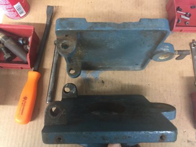
The motor did not swing much at all and in general the design of the belt tensioner wasn't very effective. Take note of the concentricity of the pin holes on the lower tabs of the motor mount. This I was going to do something about. More on that later.

IMG_4979.JPGIMG_5024.JPG
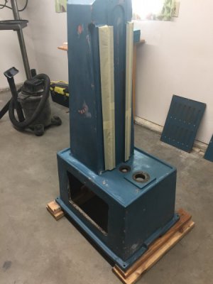
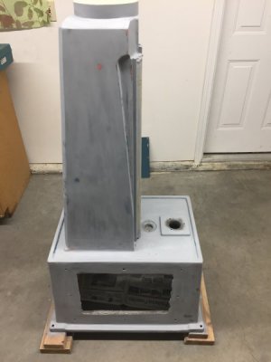
A lot of cleaning and prep work was done and I simply went with Rust-Oleum smoke gray for everything. I ended up rolling the paint on the base with a 4" paint roller and it came out looking much better than I had expected.

IMG_5551.JPG
IMG_5563.JPGIMG_5552.JPG
IMG_5572.JPG
Finally it was nice to get to the point of some reassembly.

IMG_5585.JPG
All the bearings in the knee assembly cleaned up fine with the exception for one on the crank handle shaft that was replaced.
 
The current Grizzly variant has crank wheels on it and I'm partial to crank handles. I also sourced these from Grizzle and only had to broach a new keyway in them and add the setscrew. The knee handle fit perfect as did the dial which took almost two months on back order. Again, all the bearings that could be cleaned and repacked were or else replaced as nothing spun freely.

IMG_5652.JPG

IMG_5707.JPG
Now its starting to look like something.

IMG_5550.JPG
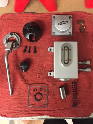
The lube oilier was scrubbed and received new o-rings and gaskets.

IMG_5708.JPG
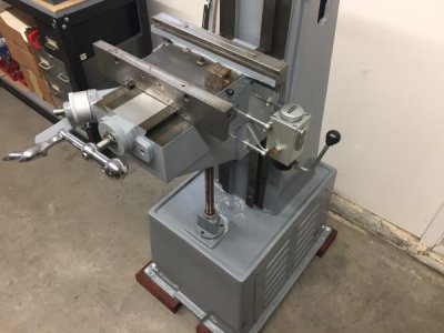
All new oil lines throughout. The pump oilier was reinstalled on some standoffs so that it would clear the future y-axis DRO scale.

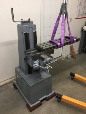
IMG_5712.JPG
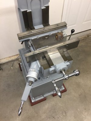
The table sliding back on. The bracket sitting on top of the mill will become the DRO and power switch mount down the road.
 
Last edited:
Tackling the motor mount.

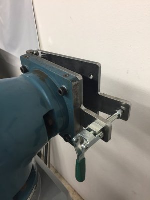
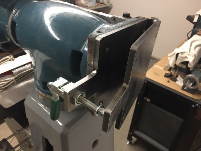
The current factory job wasn't going to do so I came up with a new one. First I took the portion of the motor mount that connects to the mill and machined the preexisting tabs off of them and faced the cast surface flat. The tab that stuck off of the side was also machined off. I'll note that I'm fortunate enough to work at a machine shop where I'm permitted to come in on the weekends and use the machines for personal use. That has been a much appreciated privilege and made many steps along the way possible.

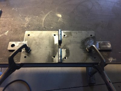
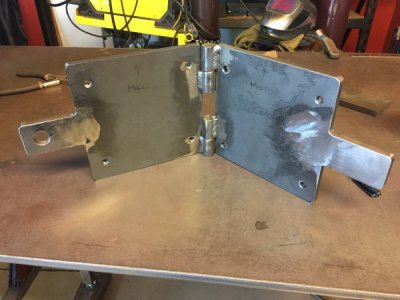
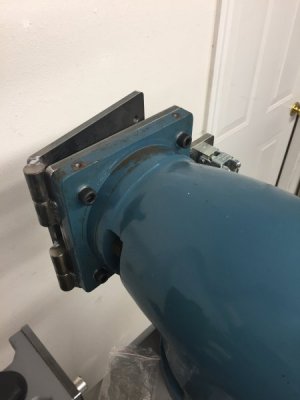
The new motor mount is made from 3/8" mild steel plate and barrel hinges so that the motor could easily be lifted on and off the machine when needed.

IMG_5788.JPG
IMG_5789.JPG

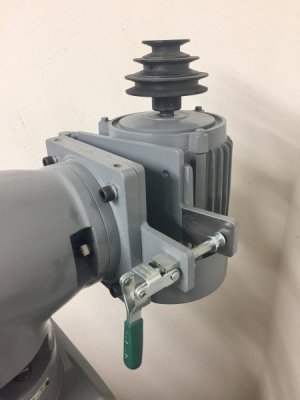
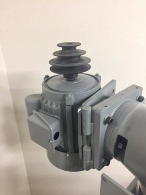
The new mill side of the motor mount is bolted over the top of the old one which is now faced and flat. A Carr-Lane push pull toggle clamp acts as the belt tensioning mechanism.

IMG_5790.JPG

IMG_5791.JPG
IMG_5792.JPG

Here's the finished motor mount with the cleaned up and painted motor installed. Worth mentioning that the motor is the only component I haven't opened up. It actually spins very nice so we'll see how it does once it gets put to work for the first time in 2+ decades.

Motor Mount 1.jpg Motor Mount 2.jpg
The carriage bolt in the end of the toggle clamp will provide a small amount of adjustment if needed in the belt tensioning.
 
I have the exact same machine. Mine is a MSC brand, and the castings are identical. Mine is probably a little older, as I do not have a one shot lube on mine. It had the ball oilers, but they did not cover several sliding surfaces.

Like you, I took mine apart to clean and improve it a bit. I added some oil retention scrape marks, added lube lines every sliding surface plus the table nuts and vertical bevel gears. Drilled and tapped the ball oilers for grease fittings and made 2 oil guns to lube it. I added 2 adjustable lock levers from McMaster to the table locks, 1 to the cross lock, and 1 to the knee lock. Much better than the stock locks. Also made some brass tips were the locks push against the gibs.

I like your motor mount. Mine is still mostly stock. I bored the off center holes in correct location (mine were not as bad as yours), added bushings to correct them. I still use the original tensioner. Never had the belt slip.

I did not find the RPM convenient so I moved my motor pulley up so top pulley groove in line with top pulley on intermediate pulley block. That gives a better choice of speeds in the 350-1100 range that I use most. I milled the slot widths in the base of the intermediate block to make them a slip fit for diameter of headed bushings, and milled the thickness so the head of the bushings are a couple thousandth slip fit. Tighten the bolts one time and have never touched them since. Just loosen the tensioner in the back and any belt change can be made by just sliding the intermediate block by hand. Very easy and recommended.

Watching to see rest of your mods.
 
It had the ball oilers, but they did not cover several sliding surfaces.

Something I thought was interesting was the internal oiling system does not deliver oil to the sliding surface of the knee gib. It actually oils the back side of the gib which isn't any help. I didn't correct this issue and sitting here thinking about it now but likely drilling the gib and adding some oil grooves to it would have been beneficial. I just made a mental note that I'll be manually putting some oil on the gib side dovetail.

I added 2 adjustable lock levers from McMaster to the table locks, 1 to the cross lock, and 1 to the knee lock. Much better than the stock locks. Also made some brass tips were the locks push against the gibs.

I elected to install my x-axis DRO scale on the front of the table to not loose the Y travel when having it installed on the back of the table. In doing this I lost both the table travel limit stops and direct access to the threaded holes on the saddle that the table locks go into. The locks I can still make work but I'm thinking I'll be making some sort of locking handle with a jog in it to clear the DRO scale. The table stops will also still be possible in another way that I just haven't thought of or seen an example of yet. Installing the Y-axis DRO scale also made me remove the table stops strip originally located there as well. More details yet to be sorted out.

Thanks for the input on the pulley group mod. I'm going to keep that in mind once I see how I like the available speeds. I've got a motor and VFD on the shelf that I was tempted to put on this rebuild but I'm thinking I want to use it on something else.
 
The original power switch is not located in a good location in my opinion. I'd prefer to have my hand up high and clear of the cutting area if I ever had to go for the switch in a hurry rather than reaching around the side next to the cutting tool. As mentioned there is a bracket I'm making (made) that will hold both the DRO head mount and the power switch up high on the machine which took care of this problem. The second problem was the large hole in the side of the casting where the old power switch used to be.

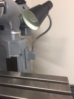
If you look back to the very first picture you'll see that the attached machine operator light was ripped out and resting on the knee. The threads in the casting were pretty bad and rather than trying to repair them I plugged the hole and painted over it. Figuring that somehow the future switch/ DRO arm would also have the light mounted to it. Instead of going that route I came up with another idea to swap the light to the opposite side of the mill and make a mount that would plug the original switch hole at the same time.

IMG_5861.JPGIMG_5862.JPG
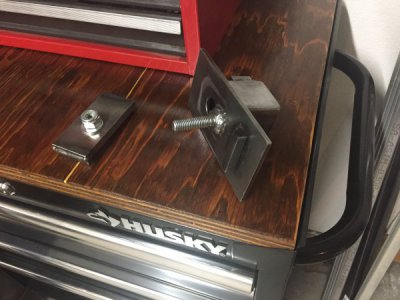
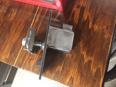
I welded together this bracket arm that bolts from the inside and clamps down on the casting.

IMG_6056.JPG
The light cleaned up nicely and threads into the top of the arm, and the wiring is still routed inside the casting. There was some waviness between the surface of the column and my plate which created small gaps in places. I had some roll rubber on hand so I cut a 1/8" thick gasket to sandwich between the two surfaces to take up the gap and keep chips from collecting here. Probably a non issue once the way cover goes on and shields this area as well.
 
I am in FL right now attending my rapidly failing father, but will send some photos when I get home Friday.

Mine did not have a factory light, but I did bolt one on the left side of casting. I also have a DRO from the PO, and the scale is on the front. That is why I needed the adjustable handle locks, as wasn't enough room under the scale to unlock and lock them. I can tell that on mine I keep the gib slightly loose, but you do need both locks tight when cutting with side of end mill.

PO never mounted the DRO head display so I made a pivoting arm base that mounts about where your light is.

Yes. I did drill thru the knee gib to get oil to the other side and added long oil grooves too.

I did not mention it, but this is my only mill. In order to mill the middle pulley base I bought a long belt that goes from motor to spindle pulley. This also provides added speed ranges even when the middle pulley is installed, I use it often.

I have designed a 3 piece riser system that will incorporate a long sliding dovetail block between upper / lower spacers so the head can be moved behind the table all the way out past front of table. Have the steel bought but have not made a chip yet. Hopefully will be my winter project. Kind of like putting a suit on a pig, but the size of the mill fits my available space perfectly.

I'm very interested to see what you've done and what you've got in mind for that head sliding setup! I have been rolling around the idea of making a riser too that would incorporate a way to adjust the head nod without having to shim.

Best of luck to you and your family with your father.

Nick
 
Back
Top