- Joined
- Feb 2, 2014
- Messages
- 1,217
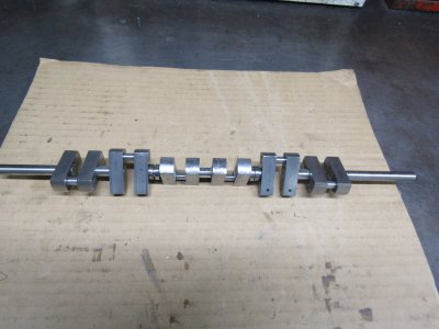
After my recent success of my 4 cylinder inline engine I decided to try a 6 cylinder. I needed a way to accurately position the throws 120 degrees and hold them exactly 90 degrees to the main shaft while the Loc-Tite was setting up. I am using Loc-Tite 620 which is fairly thick so in order to get a good coating inside the arms they need to be rotated and worked back an forth on the main shaft. The parts are assembled with the holes being a loose fit of about 0.010 which is just the opposite of what I have tried in the past when I tried making them a press fit.
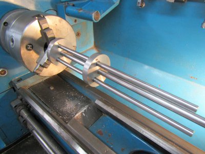
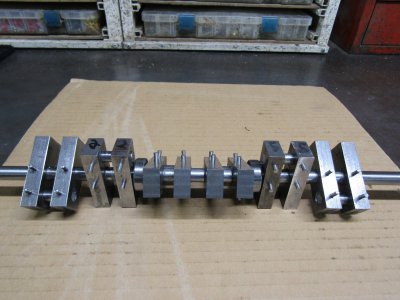
This is the setup I made for the lathe to align all the parts. The three outer rods are the connecting rod journals and are removed to allow the next throw to be installed and Loc-Tite worked in between the main shaft and the rod throw.
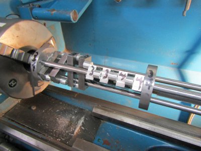
On each throw I use the tool post to hold the throws in position until the Loc-Tite setts up. Spacers are inserted between the throws to allow for the rod and main bearings. There are 4 main ball bearings two of which are installed during the glue up.
The rod journals are cut to length and installed the next day individually. When they are setup tapered pins are installed at each hole and driven home.
The pins are cutoff and filed down smooth with the throw and the main shaft sections are removed.
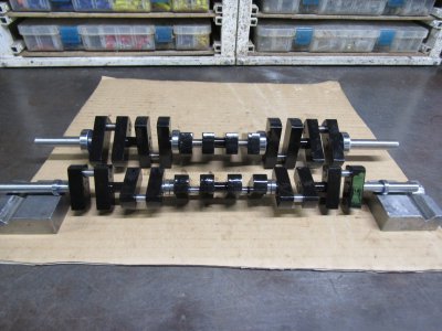
Give it a good coat of paint and the results.
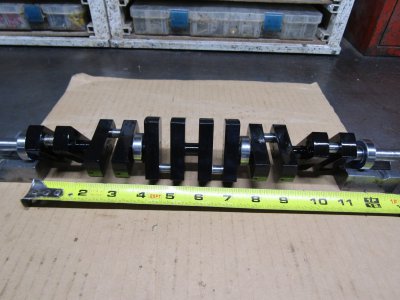
The crank runs exactly true and straight so the next job is to design an engine around it.
That is when I realized that with a 1 1/2" stroke this was going to be a huge model engine. The displacement would be around 180cc and the dimensions at least 12" by 4" X 16" and weigh around 25 lbs. I am going to put this on the shelf for future use and design a smaller and lighter 6 cyl crank.
Thanks for looking
Ray
This is the setup I made for the lathe to align all the parts. The three outer rods are the connecting rod journals and are removed to allow the next throw to be installed and Loc-Tite worked in between the main shaft and the rod throw.

On each throw I use the tool post to hold the throws in position until the Loc-Tite setts up. Spacers are inserted between the throws to allow for the rod and main bearings. There are 4 main ball bearings two of which are installed during the glue up.

The rod journals are cut to length and installed the next day individually. When they are setup tapered pins are installed at each hole and driven home.

The pins are cutoff and filed down smooth with the throw and the main shaft sections are removed.
Give it a good coat of paint and the results.

The crank runs exactly true and straight so the next job is to design an engine around it.
That is when I realized that with a 1 1/2" stroke this was going to be a huge model engine. The displacement would be around 180cc and the dimensions at least 12" by 4" X 16" and weigh around 25 lbs. I am going to put this on the shelf for future use and design a smaller and lighter 6 cyl crank.
Thanks for looking
Ray

