3D printed lathe parts.

GreatOldOne

R'lyeh Engineering Works
H-M Supporter Gold Member
Joined
Mar 20, 2014
Messages
418
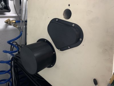
I designed and 3d printed two covers for the lathe change gear case, as I’d had two cut two holes in it to accommodate the servo and encoder on my ELS install:
8E3AF455-F1F1-4CFA-B68A-3A92C68A34A2.jpeg

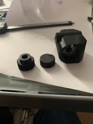
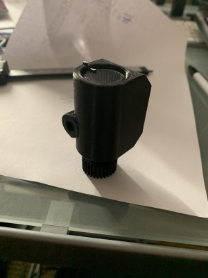
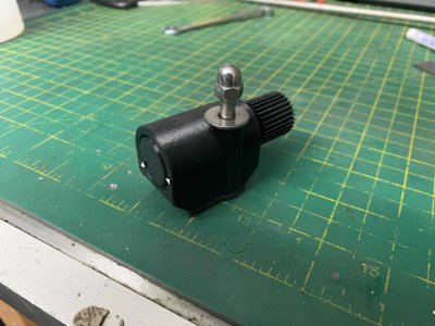
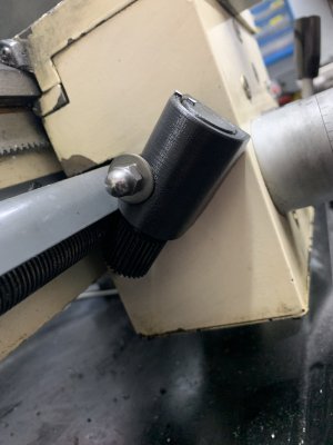
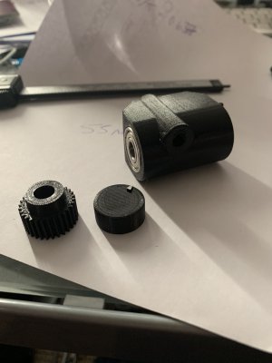
And I also designed a thread dial indicator. My lathe never had one (it’s metric), but it changing over to the ELS has meant the lathe takes longer (there‘s less drag due to the lack of change gears) to come to a stop, and I have to leave the half nuts engaged. It makes stopping in the thread relief a bit hit and miss some times. After mentioning this in the ELS thread, I was advised to look at Oxtools video on making metric threads in on an imperial lathe. He uses the dial on his lathe to resync the the carriage to the leadscrew after he disengages it prior to stopping the lathe, reversing it and then re-engaging the half nuts when the relevant marks line up.

So I’m giving this a go. I believe I only need one mark for this:

6375DE83-B44F-4033-9BC2-4605B4D90940.jpeg05019E47-D24D-424D-B72C-7FD35B640009.jpeg10B7278F-59C6-432E-9E03-854FE3594FAB.jpeg221E19D7-6C21-4CD8-88DB-1F17B5A15251.jpegB9B8518D-9D30-4B96-A377-7D94B48F40AD.jpeg
 
First off I know Absolutely Nothing about how to work one of those things so this question comes with that in mind.....Why did you just not print the "holes" so there would be no need to later cut them out?

BTW Nice work. Those printers have Truly changed the world!

Also to help with the threading issue of stopping in the relief zone, have you considered installing a spindle brake?
 
I designed and 3d printed two covers for the lathe change gear case, as I’d had two cut two holes in it to accommodate the servo and encoder on my ELS install:
And I also designed a thread dial indicator. My lathe never had one (it’s metric), but it changing over to the ELS has meant the lathe takes longer (there‘s less drag due to the lack of change gears) to come to a stop, and I have to leave the half nuts engaged. It makes stopping in the thread relief a bit hit and miss some times. After mentioning this in the ELS thread, I was advised to look at Oxtools video on making metric threads in on an imperial lathe. He uses the dial on his lathe to resync the the carriage to the leadscrew after he disengages it prior to stopping the lathe, reversing it and then re-engaging the half nuts when the relevant marks line up.
So I’m giving this a go. I believe I only need one mark for this:
Very nice work GreatOldOne !!!! :grin:
i was wondering if you could share the G-Code for the printed thread indicator????
i would love to print one of my own!
email would be the best method i'm assuming- that is unless you shared it already on thingyverse, or other
(my email is ulmadoc@gmail.com)
thank you!!!
 
First off I know Absolutely Nothing about how to work one of those things so this question comes with that in mind.....Why did you just not print the "holes" so there would be no need to later cut them out?

Erm... I think you might have gotten the wrong end of the stick there. :)

The holes where cut into the steel change gear cover, as it wouldn’t have gone back in place with the spindle encoder and servo in place. The printed parts cover up the protruding portions of those parts, and stop dust and crud getting inside.

Very nice work GreatOldOne !!!! :grin:
i was wondering if you could share the G-Code for the printed thread indicator????
i would love to print one of my own!
email would be the best method i'm assuming- that is unless you shared it already on thingyverse, or other
(my email is ulmadoc@gmail.com)
thank you!!!

I’ll put them on thingiverse and post a link up. Bear in mind that the spiral gear I printed is good for a 2mm leadscrew, and is MOD 0.7. If you want anything else you have to roll your own. I can post up my calculations - based on a lot of googling - if anyone’s interested.
 
 
Back
Top