1943 M-head Upgrades

AlxJ64

Registered
Registered
Joined
Jan 13, 2016
Messages
33
Hello all,

New guy here but only because I'm looking for a good place to hang out and talk Bridgeport Mills and share interests. I am a hobby machinist, barely... and still learning all the time. I typically bite off more than I can chew but it always makes for a good learning experience and unique results.

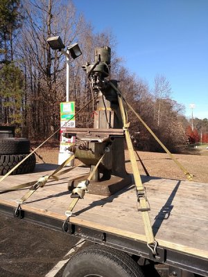
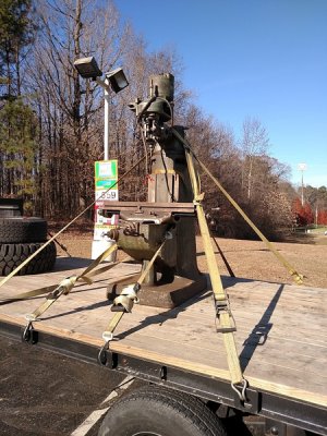
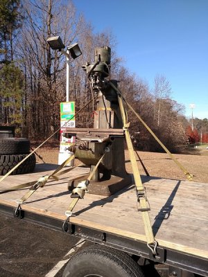
Anyways, I'm here to share my recent barn find / rescue.
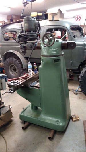
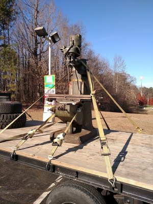
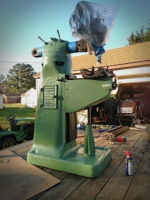
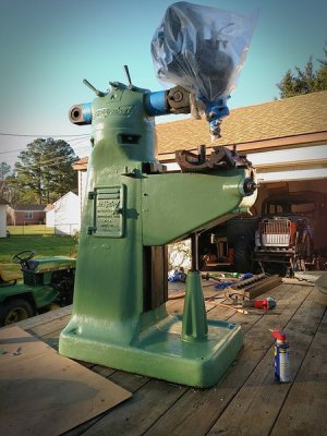
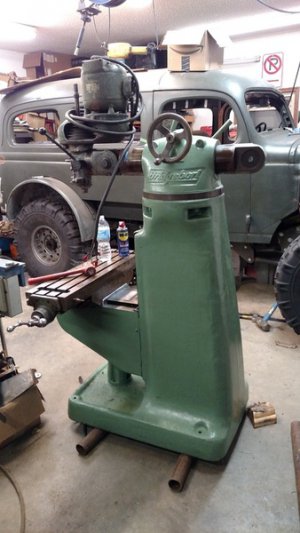
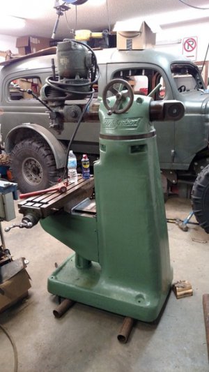
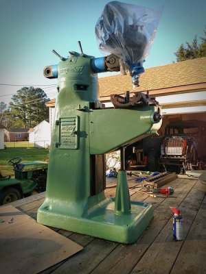
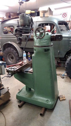
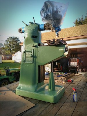
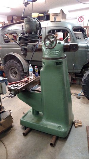
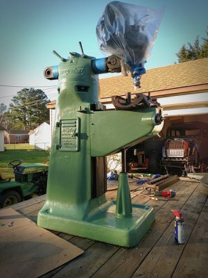
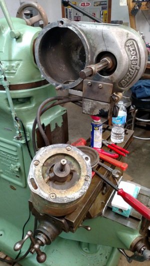
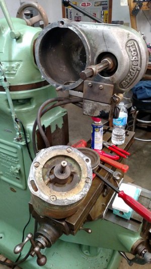
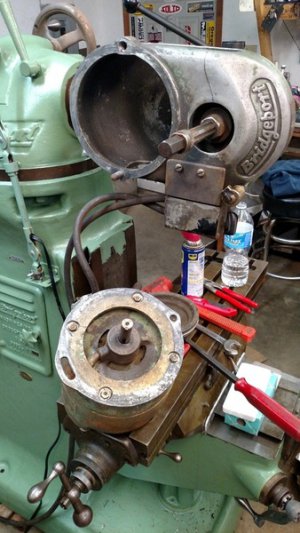
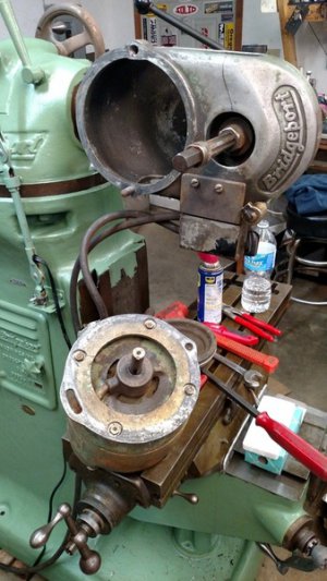
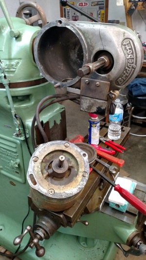
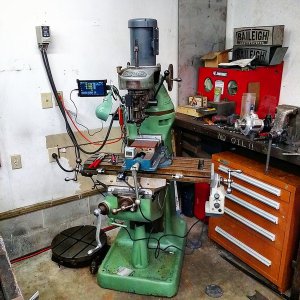
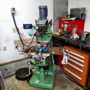
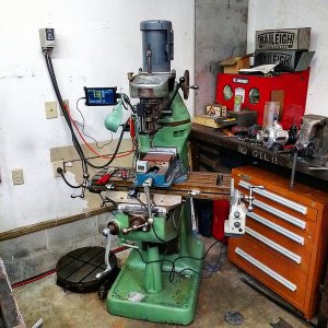
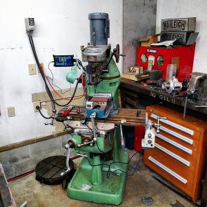
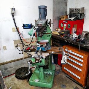
Its a 1943 Bridgeport Round Ram M-Head. The tags on it have allowed me to trace it back to being used as a pattern makers machine at the Norfolk Naval Shipyard during WWII. From there it ended up in the Shenandoah Valley, then back in Richmond, and now back a mere 15 miles from the same shipyard it was originally delivered to.

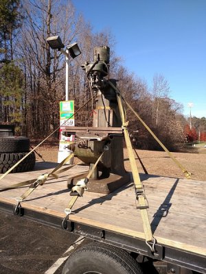
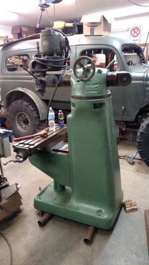
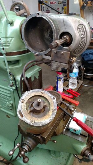
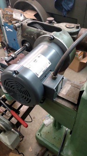
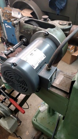
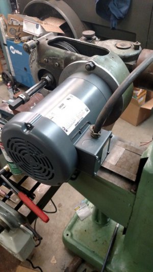
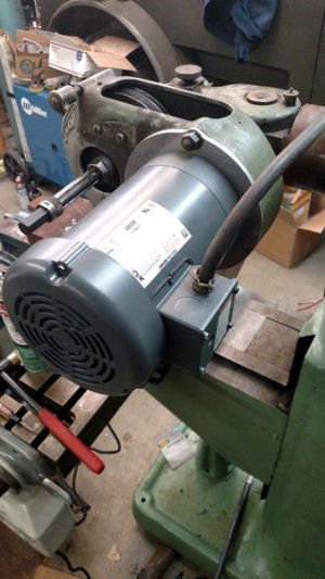
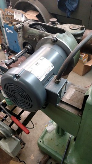
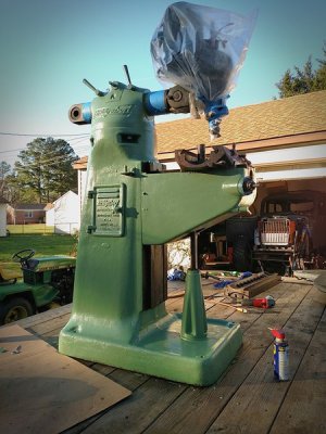
I purchased the machine from a guy in Richmond and he knew it needed work and actually had never used it. So far I have replaced the lead screw nuts in the X and Y, cleaned up the ways and gibs, etc. I have a new motor on order because when I heard this one run in his 3 phase shop it had a very notable bearing squeak. I only have single phase so its getting a 1 hp inverter rated motor with the appropriate VFD and potentiometer controls, so long as I can get it all wired up correctly. I plan on making my own mount for the C frame motor and also extending the motor shaft to the correct length because I believe the early Bridgeports used a longer motor shaft.

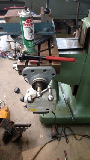
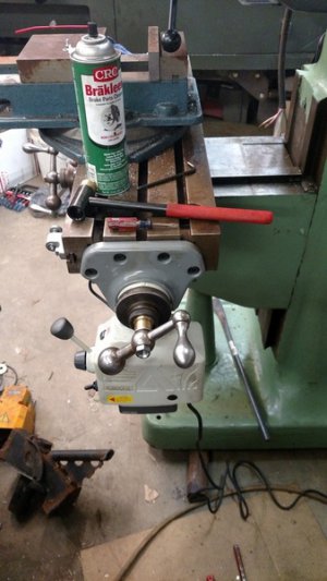
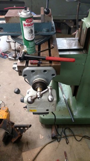
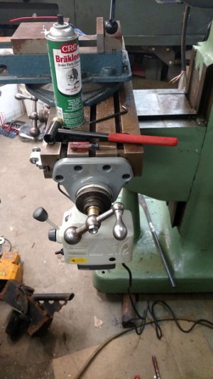
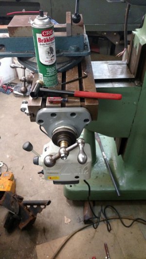
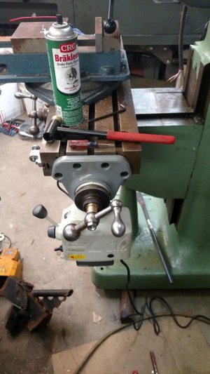
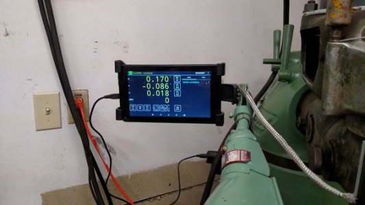
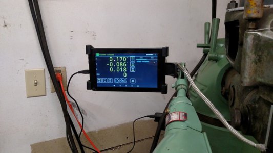
Also I am adding a DRO setup that I've been tinkering with some using a cheap set of scales and also, as blasphemous as it is, installing an import type power cross feed. I know its a WWII machine and its a Taiwanese Power Feed, but... oh well. The parts its making are to work on my old '42 Dodge Truck.
IMG_20151206_131716_zpsztmaue0m.jpg

IMG_20151227_182757_zpsejb394sb.jpg

IMG_20160106_213040129_zps1cpgbvoq.jpg

I'll keep updating as I go along with the motor swap, DRO, etc.
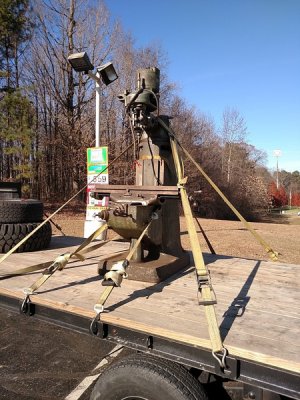
IMG_20151206_131716_zpsztmaue0m.jpg

IMG_20151206_131716_zpsztmaue0m.jpg

IMG_20151227_182757_zpsejb394sb.jpg

IMG_20151227_182757_zpsejb394sb.jpg

IMG_20160106_213040129_zps1cpgbvoq.jpg

IMG_20160106_213040129_zps1cpgbvoq.jpg

IMG_20151206_131716_zpsztmaue0m.jpg

IMG_20151227_182757_zpsejb394sb.jpg

IMG_20160106_213040129_zps1cpgbvoq.jpg

IMG_20151206_131716_zpsztmaue0m.jpg

IMG_20151227_182757_zpsejb394sb.jpg

IMG_20160106_213040129_zps1cpgbvoq.jpg

IMG_20151206_131716_zpsztmaue0m.jpg

IMG_20151227_182757_zpsejb394sb.jpg

IMG_20160106_213040129_zps1cpgbvoq.jpg
 
nice machine, I have a 1955 round ram with a J head I just picked up and I did put xyz scales and readout on the mill, I probably could use new. I also seem to have extra play in the screw for the x axis. we have used our mill and lathe for some custom parts for my 50 F1 ford and our offroad buggies. Now my boy has his own lathe and mill.
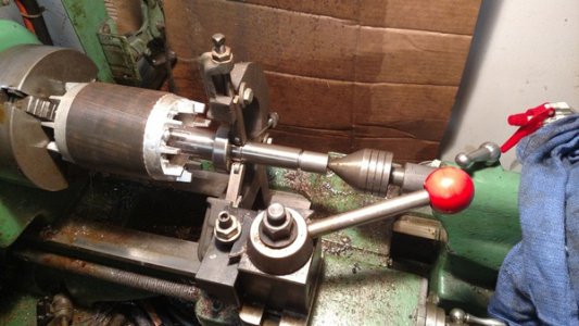
 
Started tinkering and going down the path less traveled... ie changing things rather than just replacing things.

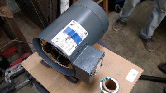
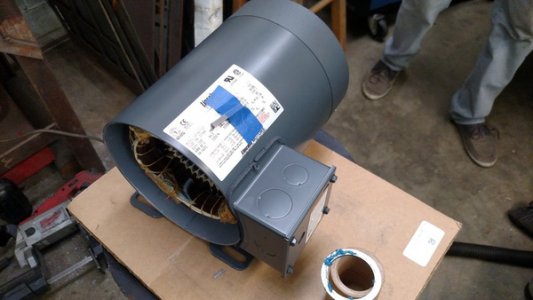
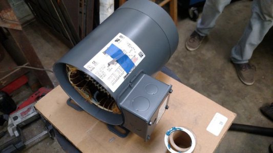
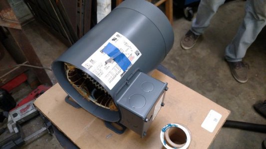
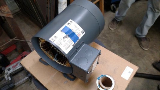
Pulled the original motor and yanked pulley so I could get comparable dimensions.

IMG_20160114_200031707_zpsnsmtydb2.jpg

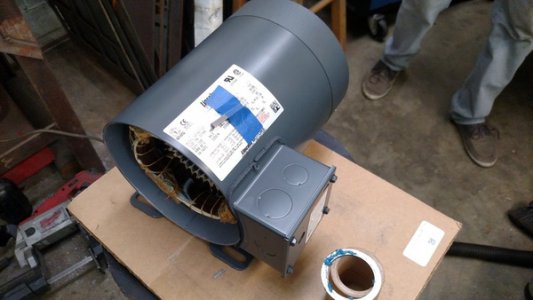
Pulled guts of brand new 3 phase motor. Have a 19 year old kid who is an ME student who is hanging out in the shop trying to learn some stuff; poor shoe choice, otherwise he's good about safety stuff.

IMG_20160114_200020787_zpsba188m5g.jpg

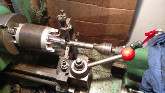
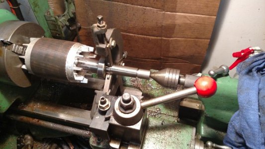
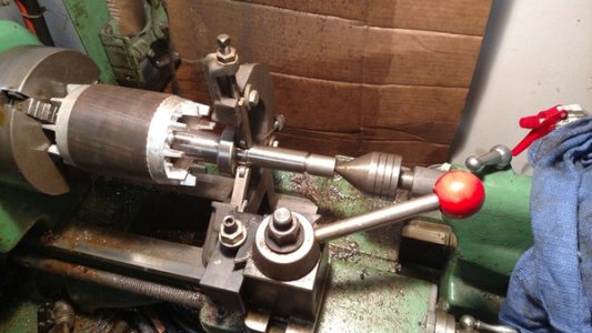
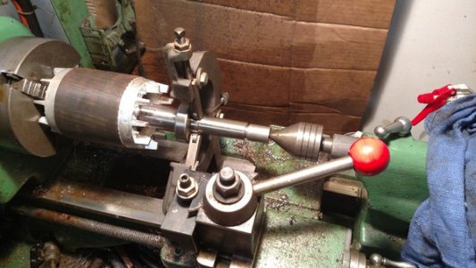
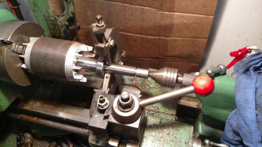
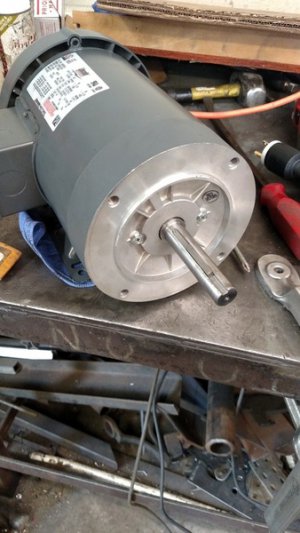
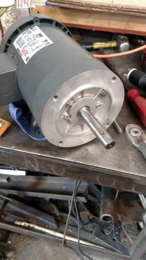
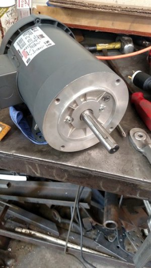
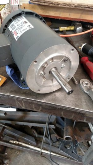
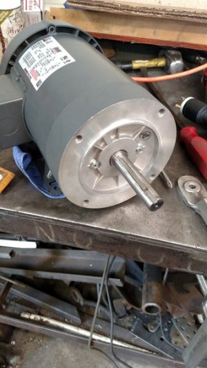
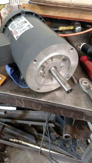
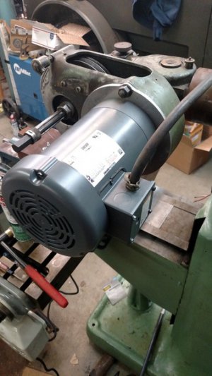
Did some math to plan for a 1/4" thick adapter plate to mate the C-frame motor to the adjustment points on top of M-head housing and determined that I need to add some length to the new motor shaft and than the new motor shaft is a touch too large. I turned down some alloy stock to 13/16" and will TIG weld it with a nice deep weld to the end of the current 7/8" dia motor shaft and then double check my shaft runout and turn the whole thing down to the correct 3/4" to fit the pulley... ohh and then re-machine the 3/16" keyway.

IMG_20160114_200047751_zpsljymdcv9.jpg

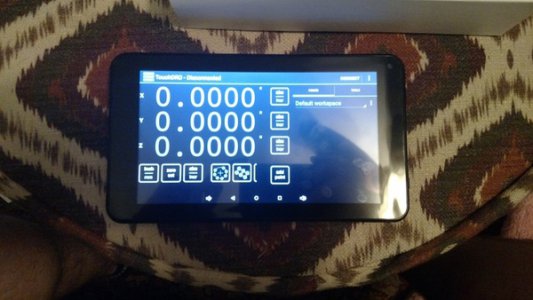
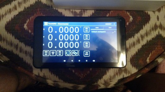
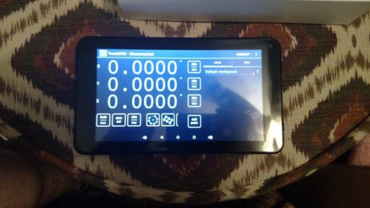
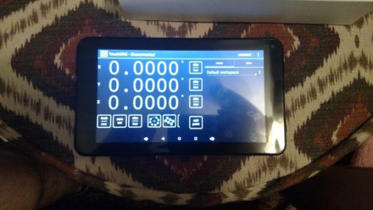
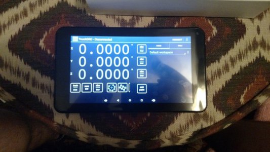
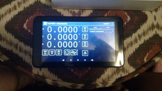
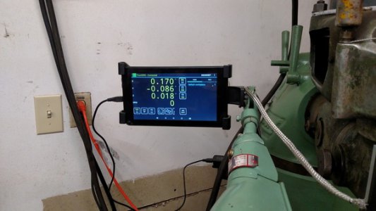
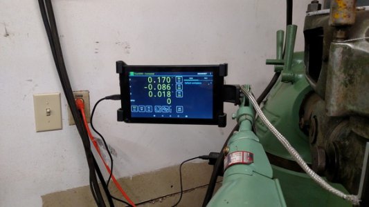
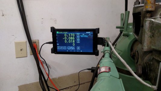
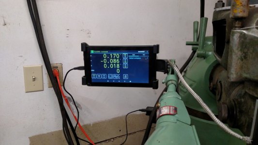
Also, here is a preview of my DRO setup. I got a portion of the program to work. It uses a 7" Android tablet as a display. Pretty neat. Has touch screen features for planning bolt circles or grids, can memorize tool offsets, and also has pretty much unlimited preset locations that it can memorize.

IMG_20160111_225429037_zps75rbdloe.jpg

IMG_20160114_200031707_zpsnsmtydb2.jpg

IMG_20160114_200020787_zpsba188m5g.jpg

IMG_20160114_200047751_zpsljymdcv9.jpg

IMG_20160111_225429037_zps75rbdloe.jpg

IMG_20160114_200031707_zpsnsmtydb2.jpg

IMG_20160114_200020787_zpsba188m5g.jpg

IMG_20160114_200047751_zpsljymdcv9.jpg

IMG_20160111_225429037_zps75rbdloe.jpg

IMG_20160114_200031707_zpsnsmtydb2.jpg

IMG_20160114_200020787_zpsba188m5g.jpg

IMG_20160114_200047751_zpsljymdcv9.jpg

IMG_20160111_225429037_zps75rbdloe.jpg

IMG_20160114_200031707_zpsnsmtydb2.jpg

IMG_20160114_200020787_zpsba188m5g.jpg

IMG_20160114_200047751_zpsljymdcv9.jpg

IMG_20160111_225429037_zps75rbdloe.jpg

IMG_20160114_200031707_zpsnsmtydb2.jpg

IMG_20160114_200020787_zpsba188m5g.jpg

IMG_20160114_200047751_zpsljymdcv9.jpg

IMG_20160111_225429037_zps75rbdloe.jpg
 
Just curious, but can't the old motor be repaired?? I like 3 phase and I use a homemade 220 volt rotary converter that has been going for some 10 years now. I did put the same touch DRO system on my last Burke Millrite mill, put it on after about 15 years without and sold it a few weeks later after getting the Bridgeport, just put on the xyz with the glass scales was about the same price I had into the touch DRO with the stainless scales I used.
 
Great job on the motor modification. I think that's the great thing about this hobby. To take some thing that was designed for something totally different and make it serve your needs or build it from scratch. Good looking Power Wagon. Mike
 
Great job on the motor modification. I think that's the great thing about this hobby. To take some thing that was designed for something totally different and make it serve your needs or build it from scratch. Good looking Power Wagon. Mike

Thanks! The truck is actually a 1942 WC53, so it predates the Power Wagon series and is what the Civilian PWs were built off of. The actual Power Wagon designation wasn't adopted by Dodge Brothers until after the end of WWII, which both this Bridgeport and the truck in my garage were born during. Truck is an October of '42 build date, and the Bridgeport SN has it November of '43.

I have a crack in the housing cover for the motor / pulleys. The crack is actually full width so I'll place a few tacks along the way starting center out and then weld it back. Hopefully it won't be too bad of an endeavor.

I TIG'd the shaft while still on the lathe so I lost very little run out on the 13/16" piece relative to needing to bring it back to 3/4" for final sizing. When I cut the keyway I somewhat expected so see myself fall short on the weld penetration at the groove weld but no such thing, there was still meat below the keyway through the welded extension. So far things are working out. Made a 1/4" Aluminum adapter plate and got the motor on. I used the old motor installed on the machine, in all of its bearing sqwaking, to machine the keyway on the new motor shaft. I bought a cheap power cross feed that I threw on there just for the heck of it. It required no modification to the machine and was a bolt on. Some of them require you cut the lead screws and install roll pins, and I wasn't cool with that idea. I started installing my scales. Need to make some brackets for the Z / quill DRO scale and then get this thing stuffed into its corner. Gonna take 3 large men and a small boy...

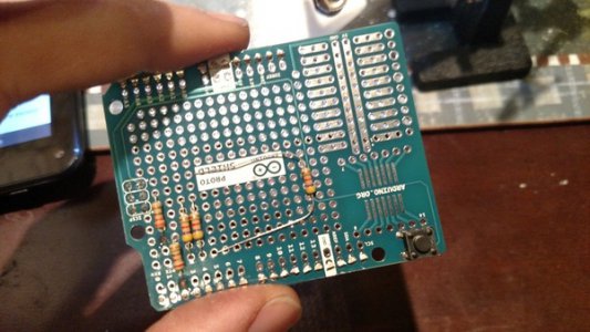
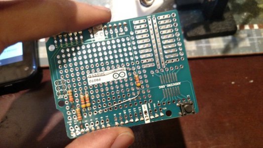
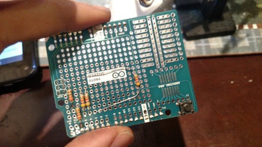
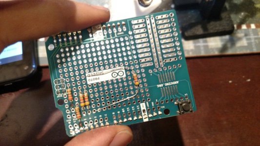
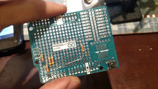
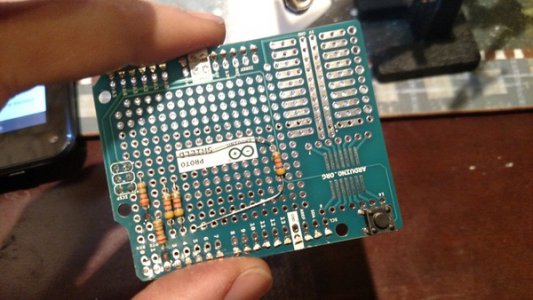
Ohh, and the Arduino / Android project... things are a LOT smaller than they look in the guide online. And also, the wire colors are not all the same on all the scales. All three of mine were different. So if you decide to do this, take apart the scale body slider housing and using the USB cable provided, continuity check each point to verify each wire for its purpose, (SRC, GRND, CLK, DATA) before doing anything else.

IMG_20160116_160828183_zps5ldczpzz.jpg

IMG_20160115_165444027_zpseujj9b2h.jpg

IMG_20160117_201601285_zpsdp6rdvxp.jpg

IMG_20160117_201550372_zpsfzccy8zz.jpg

IMG_20160116_160828183_zps5ldczpzz.jpg

IMG_20160115_165444027_zpseujj9b2h.jpg

IMG_20160117_201601285_zpsdp6rdvxp.jpg

IMG_20160117_201550372_zpsfzccy8zz.jpg

IMG_20160116_160828183_zps5ldczpzz.jpg

IMG_20160115_165444027_zpseujj9b2h.jpg

IMG_20160117_201601285_zpsdp6rdvxp.jpg

IMG_20160117_201550372_zpsfzccy8zz.jpg

IMG_20160116_160828183_zps5ldczpzz.jpg

IMG_20160115_165444027_zpseujj9b2h.jpg

IMG_20160117_201601285_zpsdp6rdvxp.jpg

IMG_20160117_201550372_zpsfzccy8zz.jpg

IMG_20160116_160828183_zps5ldczpzz.jpg

IMG_20160115_165444027_zpseujj9b2h.jpg

IMG_20160117_201601285_zpsdp6rdvxp.jpg

IMG_20160117_201550372_zpsfzccy8zz.jpg

IMG_20160116_160828183_zps5ldczpzz.jpg

IMG_20160115_165444027_zpseujj9b2h.jpg

IMG_20160117_201601285_zpsdp6rdvxp.jpg

IMG_20160117_201550372_zpsfzccy8zz.jpg
 
Appears your making good progress, and the wiring tip is very useful. That's one of those things that could really drive you round the bend figuring out. Mike
 
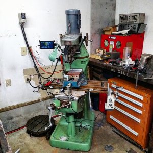
Since I had some friends over, they helped me push this thing into the corner. I have a very small shop so this is the best I could fit it. I still am going to pull the head to weld the crack but had to plug it in to see things working. The DRO is still getting some Electro mag interference from the 3 phase motor so I have some more insulating and isolating to do on that. It works perfectly with the motor off. I think the 3 phase motor is messing with the transmitter signal (bluetooth) so I may just hardwire it.

IMG_20160123_181920_zpskru1xqwq.jpg

IMG_20160123_181504313_zps5peesuog.jpg

IMG_20160123_181920_zpskru1xqwq.jpg

IMG_20160123_181920_zpskru1xqwq.jpg

IMG_20160123_181504313_zps5peesuog.jpg

IMG_20160123_181504313_zps5peesuog.jpg

IMG_20160123_181920_zpskru1xqwq.jpg

IMG_20160123_181504313_zps5peesuog.jpg

IMG_20160123_181920_zpskru1xqwq.jpg

IMG_20160123_181504313_zps5peesuog.jpg

IMG_20160123_181920_zpskru1xqwq.jpg

IMG_20160123_181504313_zps5peesuog.jpg
 
Back
Top