14x40 Lathe Improved Carriage Lock

petertha

H-M Supporter - Gold Member
H-M Supporter Gold Member
Joined
Jan 15, 2016
Messages
996
After some recent photo rummaging, I realized I never posted my improved carriage lock pics, so here you go.

The stock mechanism was always kind of a vague & iffy. Sometime it would tighten sometimes not. Pushing on the nut & tightening simultaneously seemed to work best. But if the nut ever became loose more than a full turn, the entire clamp & post would extend out of the carriage hole & you had to fiddle it back into position. Even when locked, the carriage never really felt too secure. And sometimes it would spin & partially grab just traversing the carriage.

I had to remove the carriage for another reason so this provided opportunity for a closer look. Hopefully the pics tell the story. The design is not the best. The foot only provides minimal contact area to the casting bed. I think the milled flat on the foot segment is somehow intended to be contained by the front of carriage housing, but it just didn’t match up in my case for whatever reason. The good part is the hole is drilled nice & close to the bed lip.

2017-03-25_15-52-43.jpg


IMG_5902_edited-1.jpg


IMG_5899_edited-1.jpg


IMG_5897_edited-1.jpg


IMG_5895_edited-1.jpg


IMG_5875_edited-1.jpg
 
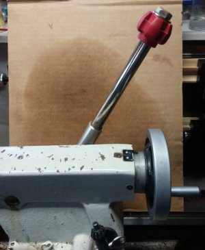
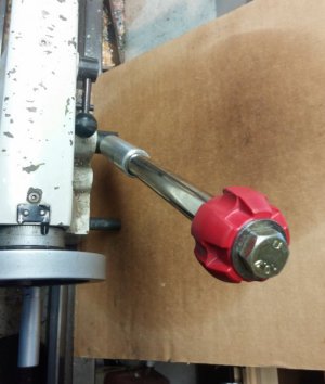
So here is what I came up with. A blocky more rectangular foot which provides significantly more contact area. It cannot rotate out of clamping position because of the square foot shape & small clearance gap. For the clamp post I used a double-threaded 0.250” hold down rod from a milling strap clamp kit & it slides inside a turned bushing which is light press fit in the (metric) hole in the carriage casting. This keeps the movement very nicely aligned. I used a hex nut to either finger tight or a wrench if required. Now it has a very positive feel & when its backed off it just slides with no drag. I can also use one of those commercial low profile spring release detent handle clamps on the top threads, but I'm not quite sure I like it yet. The nut is a bit cleaner & the wrench is always handy.

Anyway, hope this helps if you have a similar issue your lathe.

IMG_5963_edited-1.jpg


IMG_5964_edited-1.jpg


IMG_5967_edited-1.jpg


IMG_5968_edited-1.jpg


IMG_5969_edited-1.jpg


IMG_5979_edited-1.jpg


IMG_5980_edited-1.jpg
 
Oops. Forgot to mention I first tried making the threaded rod portion by die threading some drill rod & that's what's in some of the test fit pics. That didn't work out too well (long story) so that's when I switched to a commercial hold-down rod & cutting to length. The assembly was blackened (looks better in real life!) :)

IMG_5970_edited-1.jpg


IMG_5971_edited-1.jpg


IMG_5977_edited-1.jpg


SNAG-3-26-2017 0000.jpg
 
One more item that needs attention on mine.
I had forgotten that mine isn't working until I started going through your posts on your 1440.
Don't suppose I could talk you out of your drawings? :grin:
 
Here you go. Pardon the 'homebrew dimensioning standards'.
Knowing the variation in these lathes, yours may well be slightly different, but at least it gives a starting point.
 

Attachments

  • clamp foot.PDF
    41.2 KB · Views: 401
  • Assem1.PDF
    74 KB · Views: 488
  • apron bushing.PDF
    38.9 KB · Views: 409
Thanks Peter! It's very helpful to have a reference to go-by instead of re-engineering it.
 
Finally did one up for my Brimingham. The Half-Nut assembly went wonky and I had the carriage off.
I had to get it back up and running quickly so mine is not as elaborate.
I had a 10mm bolt laying in the bin that was almost perfect. The shank is around .360" so I wrapped some shim stock around it to make up for the difference when I assembled it.
Functions much better now.
Thank you again for the drawings Peter, saved me time when it needed to be saved.

1529710254331.png
 
My pleasure. I'm really happy with this mod on my lathe. So simple & very positive lock-down, it makes you wonder what they were thinking with that weird lopped off cylindrical contraption.

When I find a suitable chunk of steel I'm going t improve the clamp for my underside of my tail stock. That's another thing that's been bugging me. Always coming loose, never locking positive, ill-fitting on the underside of ways. Oh well, we have machines to make better machine parts right? LOL
 
Wait, hold on a minute - there's a clamp on the tailstock? Where did you see this? :grin:

You're right, it needs a better designed plate.
I've tried tweaking mine a few times now. Had to take a die grinder to the inside of it because the cam-lock bolt was rubbing against the casting housing.
Really need to disassemble it and re-engineer it but I'm hesitant to do that because it is lined up nicely and I'll just mess that up.
I added an extension handle because the original was messing with my shoulder.

0623181207.jpg........0623181207a.jpg
 
Back
Top