- Joined
- Jan 23, 2012
- Messages
- 1,216
 CRAFTSMAN / ATLAS 12"
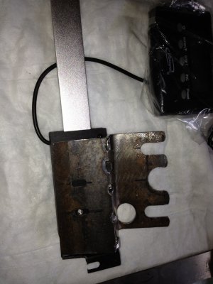
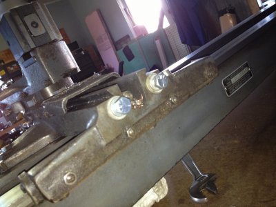
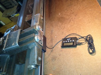
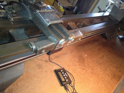
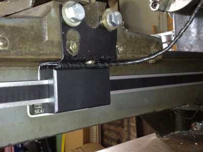
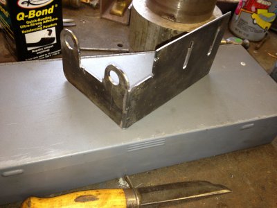
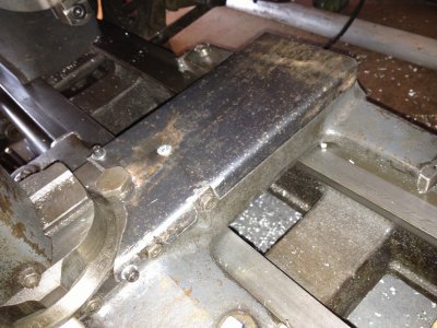
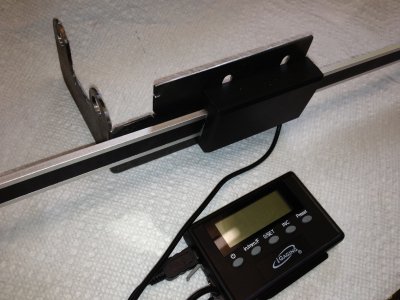
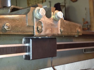
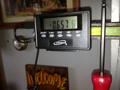
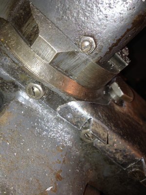
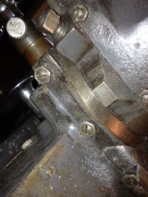
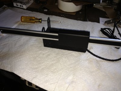
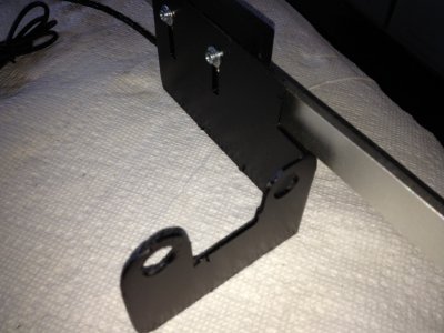
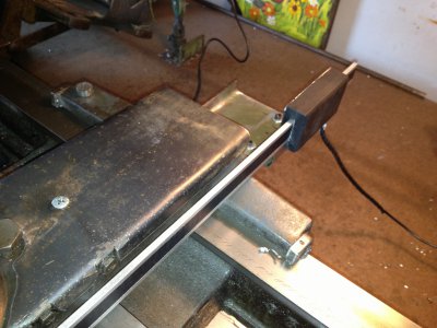
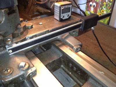
finally I have both "x" and "y" dros mounted and operating on my the 12" atlas craftsman lathe. the bed travel on mine is about 42 inches so i installed the 36" long dro scale. its actually about 40" long. i made a "z" shaped bracket that i had to weld one leg onto that mounts on the back of the carriage and straddles the gib adjusters that are there, bolting to the existing holes for attaching the taper attachment. at least i think that"s what the holes are for.
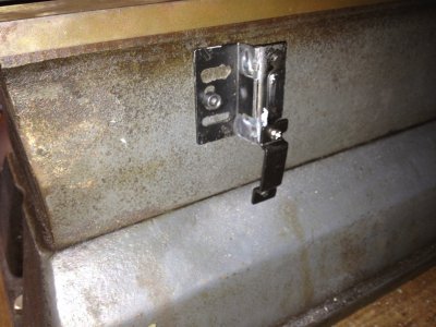
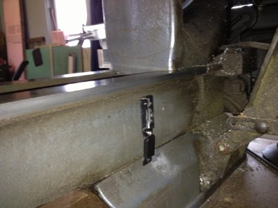
I needed to make it with a u-shaped cut out for the lead screw, and the hight above the mounting holes is critical to not be too high. i made slotted holes in the bracket to hold the scale reader in positioin. the scale itself was fastened to the bed of the lathe on both ends locating the height of each end using the carriage as ref. on each end. I have pictures of those too. the whole assembly tucked far enought under the rear "way" that i don't believe there will be any problem with swarf. i also added a protective plastic coil over the wire that comes out of the reader, and located it in back of the reader so it would not be flexed where it enters the reader. . . . seems to work great.
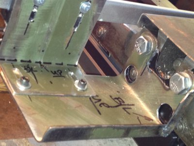
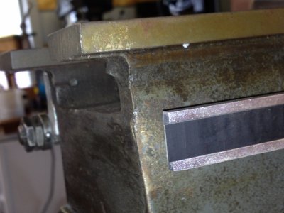
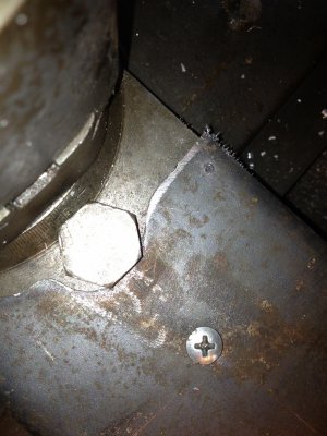
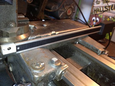
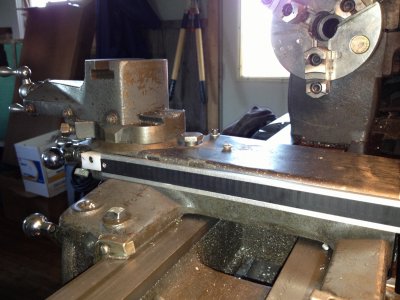
the crossfeed was more of a challange. i have it installed on the right hand side of the carriage and by doing so i have lost about 1" of travel due to interference with the tail stock. for my use that will not be any problem. first off i made cover that replaces the little aluminum one that sort of protected the lead screw. i folded the sides down and notched the right hand flange in a couple places for the gib adjustment screws and to make it as narrow as i could. i drilled and tapped a #8-32 hole in the top and the r.h. side of the carriage casting to hold it in place. i also used the original top fstening screw with a longer machine screw. the reason for this cover is to have a large & ridged area to fasten a protective cover over the scale and reader..... if i decide i need one. right now, I think I will leave it open and see if any problems develop.
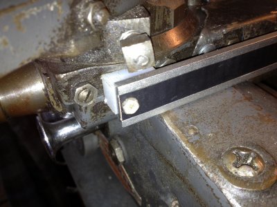
i drilled and tapped another #8-32 hole on the cross feed side rail to fasten a nylon spacer about 1/2 thick. i will mount the end of the scale to this nylon with a small metal screw.. the scale is aluminum and drills very easy. to secure the nyon spacedr to the side of the cross feed casting, i drilled and countersunk a hole for a number 8 socket head screw.
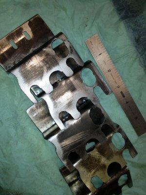
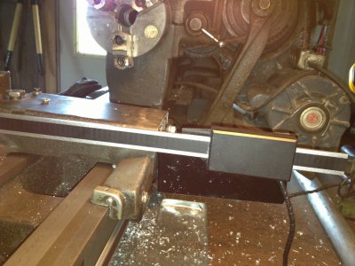
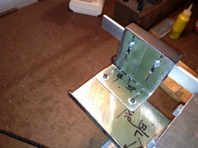
the rear bracket that holds the reader is made similar in shape to the first one made for the reader on the table and fastens on top of it with the same cap screws. i attempted to make it one piece, and I enclosed a picture or it, with a 90 degree bend, to hold the reader but it was not adjustable without using shims or washers under the reader head. i eneded up making a two piece bracket that will allow adjustment left and right, plus up and down for the reader.
after screwing the bracket on to the rear of the lathe, i mounted the end of the scale to the nylon spacer with the sheet metal screw described above, attached the reader to the second part of the brcket a bit loosely and cranked the crossfeed as far in as it could go. i adjusted the reader on the l-shaped vertical bracket so the scale was level with the cross feed, made a couple witness marks , backed off the cross feed and tightened all the mounting and adjusting screws. and I silicone the cord inlet on the reader head, even though it is mounted stationary. notice I did not support the far end of the scale. why would that be necessary I said to myself.
perfect !
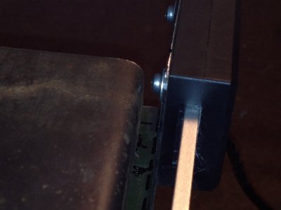
and there is about zero clearance between the little screws that hold the reader to the vertical mount, and the top cover . the little screws that come with the dro's are 3m .5 by ???? long. I bought a box of longer ones that I needed to use with my brackets.
all in all i am quite pleased with my project and i have made few extra brackets and mounts.
sorry im so long winded. i think there are about 25 pictures attached. (if i can get them to upload.)
i have sheet metal and sheet metal tools that made this pretty straight forward once a design was established. I think this type arrangement would work for most smaller lathes basically the same way.
now its a pretty simple job to take them off and re=install should i need to use the machine with different accessories.
next will be details for a rong fu 30 mill in case anyone is interested.


