I’ve been wanting to make an interesting form that used eccentric turning. I wanted to make it as long as feasible on my hobby machines and I would display it vertically. I did some research on cams and got to thinking that they are too solid of a piece. That led me to crankshafts that were much more “airy”, and certainly more difficult to make. I remembered seeing a thread once on one of the model engine sites where a guy made a V-12 crank and he made a special jig to help turn it.
I suppose there are many ways to do this but they would involve a lot of dial indicator work setting up each crank pins off-set. The fixture this guy made was a big block of steel that was turned and bored with the crank throw dimension machined into it so it eliminated the individual set-ups. I don’t know if it was his idea, or if it was commonly used amongst the model motor heads. There were no plans, instructions or dimensions, so all I had to go on was a couple of photos he posted. They didn’t show how he supported the right end either while turning it.
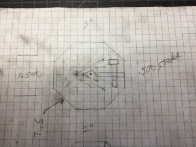
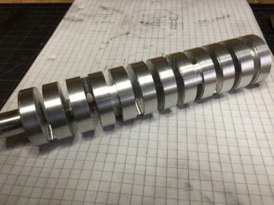
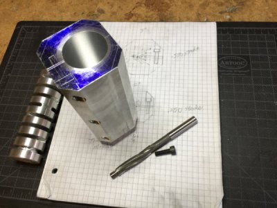
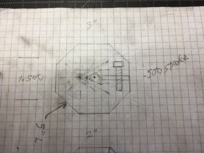
I made a sketch to get some basic dimensions on paper and decided to make a 1.500” crank with a .500” throw. For the amount of rod journals, I decided on 10 cyl. to get the height I was looking for. The basic concept for the fixture is you don’t have to reset the throw for each journal once it’s set-up. Instead, you turn the crank to an index mark on the fixture.
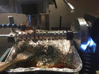
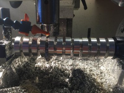
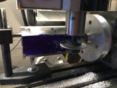
I remember the guy used the mill to rough out the crank pins, so that’s what I did. I turned a length of 6061 and turned it to 1.500” with a 3/4” tenon to hold it in the rotatory table (RT). I decided to set my journals at 90* apart. I roughed out the journals according to my sketch using a 3/16” end mill with some cutting oil. I plunged through the shaft and then used the RT to turn the shaft to my dimensions providing a rough cut “V” to finish machining on the lathe. I turned the RT 90* and keep this procedure going for all 10 journals.
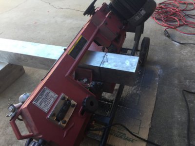
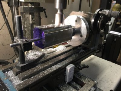
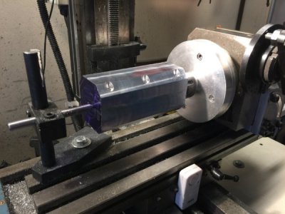
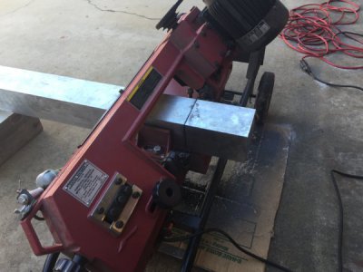
Then I made my turning fixture out of aluminum because I have a 3’ bar of 4” X4” 6061. I cut off a chunk with my horizontal bandsaw, turned a ¾” tenon to hold it, and mounted it in my RT with collet adapter.
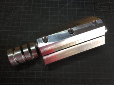
I knocked down the 4 corners, but left them big because it really didn’t matter. Then I put it in the lathe and bored the 1.5” hole through it with a .500” off-set from center. After I was done with the hole, it went back to the RT to drill, counterbore and tap the 3 pinch bolts, and slit the length open for squish clearance. Back to the lathe to knock off the tenon and honed it to a perfect slip fit.
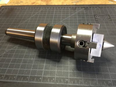
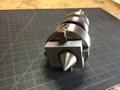
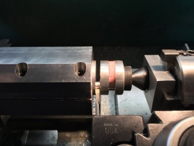
To support the right end, I used my off-set turning fixture. I made this some time ago and it came in handy. It’s a rotating tail stock with a 3” 4-jaw independent chuck. I made a live center block to mount in my live chuck, adjusted to a .500” throw. This set-up provided the much-needed support to the right side.
Disclaimer: This was made as an art project, and not to be used in a motor. I would never recommend using an aluminum crank shaft in a running engine, especially w/o main bearings!
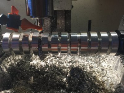
As I turned the rod journal throws the project piece started to get real flimsy, sort of like turning a wet noodle. So I came up with some ¼” thick rubber grommets/cut it half to add some rigidity. This allowed me to turn all of the throws on one end, and then flip it around to turn the other end. All of the turning on the crank pins was done with my 3/16” parting tool.
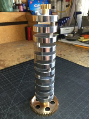
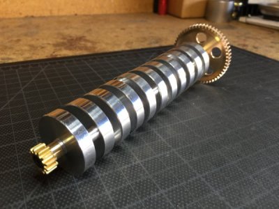
As I was working on this, I figured out how I wanted to display it. I decided to make the top and bottom mounts out of brass gears to represent a crank’s pinion gear and flywheel. With the bottom 24T gear, I installed two small, sealed ball bearings so it would turn smoothly. I used a 12T pinion gear for the top knob. I didn’t take the time to build them from scratch, so I bought them online from Boston Gear and then machined every surface on them to remove all casting marks and sized them to my crank.
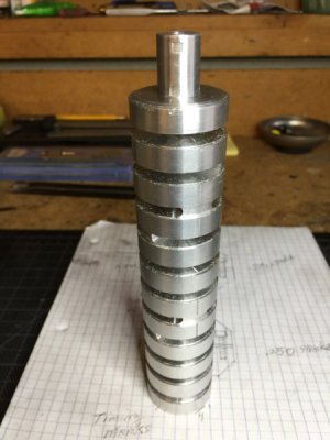
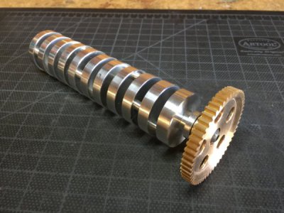
I finished the project with bright, polished outer edges of the crank counterweights. I got a very nice finish on the inside surface of the counterweights so I decided to leave it that way. I left a fine sanded surface for the journals, like a real crank.
It turned out very cool. It’s fun to turn the pinion gear to show-off the 90* pins floating by. It also looks very cool on my projects shelf.
Rick
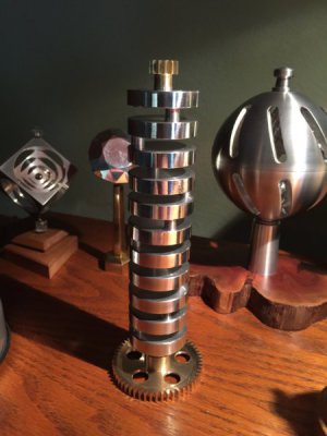


Last edited:

 Beautiful work.