1:14 Scale IH 350 Payhauler Dump Truck - Radio Control

Sparkycuda

Registered
Registered
Joined
Jan 3, 2013
Messages
8
I found this website in the hopes of learning more about machining and it has not disappointed me. I have a Speedway 7X12 lathe and Harbor Freight Mini mill that I'm learning to use. Have been a model railroader since 4th grade and always built models, so when I stumbled across larger scale RC construction machines, it was a natural fit for me. Anyway, if you have an interest in such things I recommend www.rctruckandconstruction.com. There are many machinists on the forum and excellent models.

Having grown up with IH construction equipment, I chose their 1970s, 50 ton, 4-wheel drive dump truck as a model to build. I'm using purchased axles (modified), 3-speed transmission (also modified), and hydraulic pump, but am building the frame, suspension, cab and body, and hydraulic cylinders. It has been an interesting build, having to learn use of the lathe and mill as I go along.

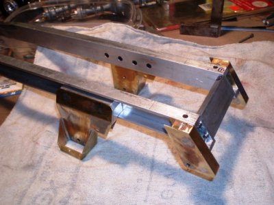
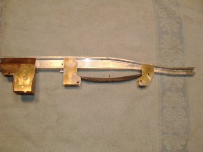
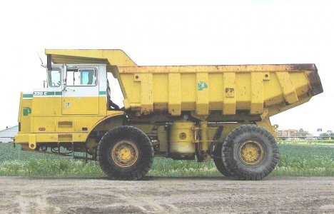
This is the prototype 350 Payhauler 00 Payhauler 350C image.jpg The frame rails are modified aluminum c-channel.
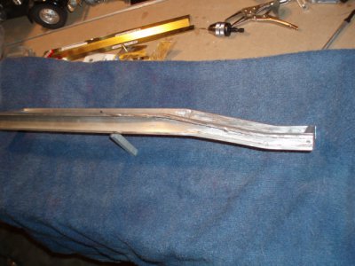
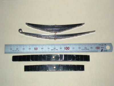
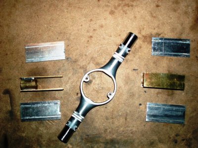
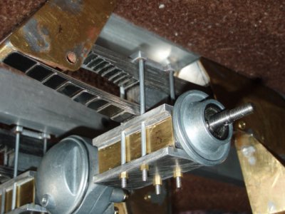
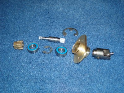
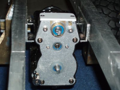
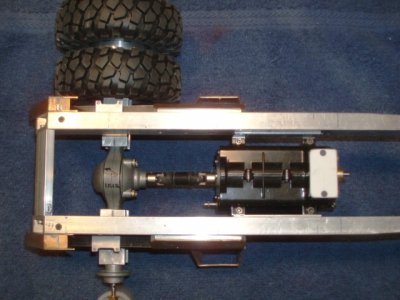
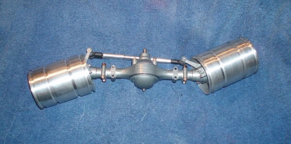
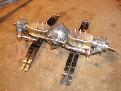
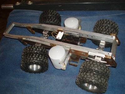
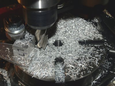
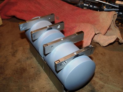
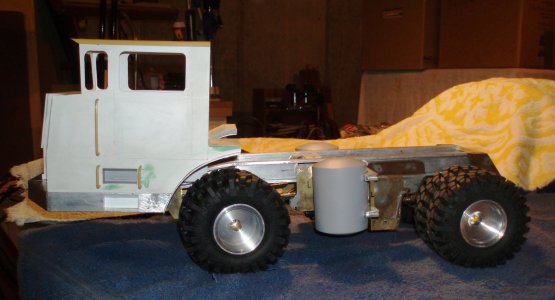
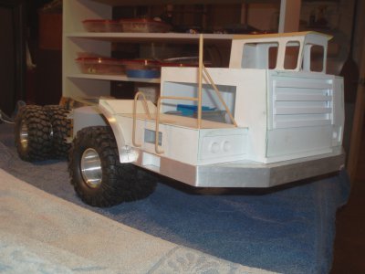
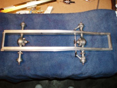
01 Frame Rails.JPG General layout of the frame and axles. 03 Frame & Axles.JPG The rear rear spring and hydraulic cylinder brackets 04 Rear Spring Brkt & Hyd Cyl Mount.JPG Rear spring brackets mounted.05 Frame Rear Axle Brkts.JPG Rear springs-Main & Overload.06 Rear Springs - Main & Overload.JPG Modified axle housing 07 Rear Axle Modifications.JPG Rear axle & springs. 09 Rear Axle & Springs.JPG 1st Wheel completed 10 First Wheel.JPG Trans input shaft & pinion. 11 Trans Pinion Shaft - Parts.JPG Transmission modified & mounted. 12 Trans Case Modified for Pinion Shaft.JPG Rear driveline 13 Rear Driveline.JPG Front Spring mounted. 14 Front Spring  Mounting.JPG Front axle & wheels.16 Front axle & Wheels.JPG Front Axle & springs. 17 Front Axle & Springs.JPG Chassis18 Chassis Top View.JPG Milling fuel tank brackets. 19 Milling Tank Brackets.JPG Fuel tanks & brackets.19A Fuel Tanks & Brackets.JPG Cab & Chassis 20 Cab & Chassis.JPG20A Cab & Chassis - Top.JPG Cab & mirror mount
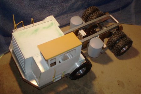
21 Cab Railings & Steps.JPG

00 Payhauler 350C image.jpg 01 Frame Rails.JPG 03 Frame & Axles.JPG 04 Rear Spring Brkt & Hyd Cyl Mount.JPG 05 Frame Rear Axle Brkts.JPG 07 Rear Axle Modifications.JPG 06 Rear Springs - Main & Overload.JPG 09 Rear Axle & Springs.JPG 10 First Wheel.JPG 11 Trans Pinion Shaft - Parts.JPG 12 Trans Case Modified for Pinion Shaft.JPG 13 Rear Driveline.JPG 14 Front Spring  Mounting.JPG 16 Front axle & Wheels.JPG 17 Front Axle & Springs.JPG 18 Chassis Top View.JPG 19 Milling Tank Brackets.JPG 19A Fuel Tanks & Brackets.JPG 20 Cab & Chassis.JPG 20A Cab & Chassis - Top.JPG 21 Cab Railings & Steps.JPG
 
Last edited:
Man thats great and the detail is out of this world. Also looks like you have the lathe and mill figured out.

Be watching for the finist truck.

Paul
 
Holy fricken crap that is cool!! PLEASE keep us posted on your progress!


Bernie
 
Naaaaaayce!
I am following this thread!:man:
 
Super cool! :thumbzup: I'll be watching the rest of your build closely as well.

Thanks,

-Ron
 
Aw, nuts. Now I definitely need a bigger shop. I could really (but better not) get into that. Nice work.
 
Great work on the Payhauler. Could you give us a little information on how you constructed the frame, materials, technique etc.
Thanks,
gbritnell
 
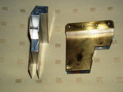
Thanks to everyone for the compliments and encouragement. The frame is 1"X1/2"X1/8" aluminum channel with the front dropped and reduced in height. I did this by sawing the web at the flanges of the channel, removing the web, cutting plate to match the dropped contour needed, then brazing the shaped web in place. The frame is bolted at front and rear crossmembers. Notice the odd brackets that are the forward spring hangers for the rear axle - they are also part of the fuel tank mounts and are the lower hydraulic dump cylinder mounts. I needed soldering capability but was not confident in machining thin plates from solid stock, so I used a hybrid approach. The center of the mount is machined aluminum, skinned with sheet brass. The two are screwed together with 1-72 flathead brass fasteners, the heads being filled with solder after installation. The rear spring mounts are constructed of 3/8" square and sheet brass, as are the front spring mounts. All mounts are screwed to the frame using hidden fasteners are much as possible. Springs are made from steel banding material, cut to width and center drilled. Rear units have main and helper leaf stacks - front are parallel leafs. 3-speed tansmission is from a Tamiya Semi Tractor that is modifed with a longer main shaft to give front and rear outputs to power the 4-wheel drive. A servo in the right fuel tank (tanks made from 2-1/4" PVC) shifts it. Normally, the drive motor mounts directly to the transmission, just above the input, but I needed the trans to be flush with the frame rail. Besides, the real truck has a prop shaft from the engine to the centrally mounted transmission - I just copied that setup. The pinion gear needed its own shaft and bearings, a housing and u-joint accommodation. This was fabricated using sealed bearings, e-clips, brass tube and plate, and a steel shaft. The motor is a 7.4v-85 turn RC crawler item with a 3:1 reduction. I calculated RPM, gear reduction and tire diameter so top speed of the model will be, in scale, same as top speed of the real one - 42 MPH.

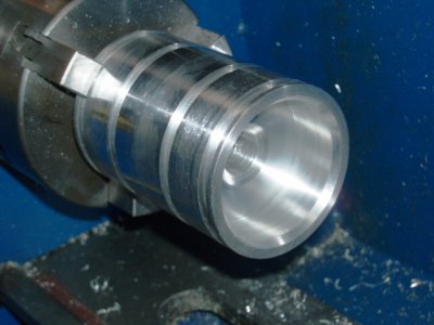
The axles are RC-Channel brand, made for Tamiya Semi Trucks. The spring mounts did not match what I needed, so I milled them off and fitted aluminum and brass plates around the tubes to simulate the cast housings of the 1:1. This allowed the springs to mount correctly, using 2-56 threaded tie bolts. Wheels are turned from 2-3/4" aluminum, with grooves matching tire bead size. Tires are from an off-road RC truck, that are similar to the real tread. Cab is made of .080" styrene with brass roof and hand rails are 3/32" brass tubing. It sits on a 1/2" aluminum channel subframe that is hinged to the front frame, so it can tilt forward for battery and component access. Fenders are aluminum sheet screwed to the cab.

The next major items to make are the dump body and hydraulic cylinders. Hydraulic pump, valve and lines are purchased items. Of course, there are gobs of details to be added: cab interior and windows, fuel tank necks & caps, wheel center covers with studs, clamps and nuts, etc. Headlights will be high-intensity white LEDs. A sound system may be added, eventually.

The project has been slower than I had hoped, but I've been learning lathe and mill use going along, plus modifying components (with the necessary figuring to make them work), and now learning about radio controls. It has been fun so far and it was very fulfulling when I actually drove it across the floor the first time.

Ken
 
Are you working from CAD drawings or just "picture and caliper"? It would be great to have a full set of drawings and a good write-up of the the "off the shelf" parts used so the rest of us can benefit from all your hard work. :whistle: :biggrin:

Looking forward to more updates.

Thanks,

-Ron
 
Back
Top