07301 missing set screw?

92VwGTI

Registered
Registered
Joined
May 31, 2018
Messages
36
Hello everyone,

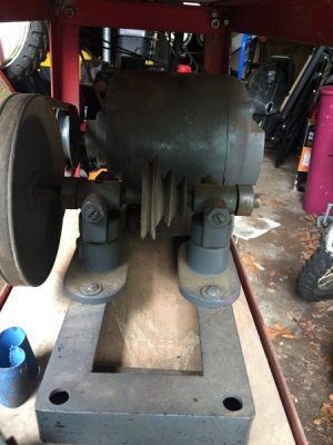
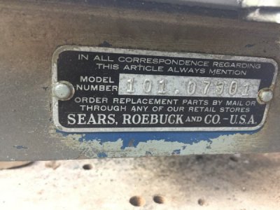
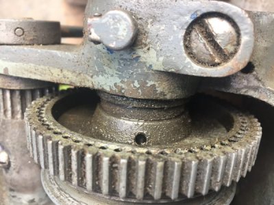
I just picked up this Craftsman 101.07301 and am in the process of tuning it up to learn the hobby. While going over the machine I noticed this hole for a set screw in the bull gear but the set screw is missing. Is this just a case of a universal part that doesn’t need the set screw for my application or is it truly missing? Thanks in advance.
D010DFF5-C11A-4603-BCE6-F3301D0CF2F2.jpeg

8B7832D9-4AE0-4C46-9988-17051D5A2AD4.jpeg
 
Thank you. Does anyone know the size of the set screw off hand? I already have an oil hole screw that a previous owner over tightened and split that I need to replace.
 
The screw that goes into the hub of the bull gear is a #8-32 cup point socket head set screw.

The oil plug screw is a #8-32 x 3/16" headless cup point set screw. However, I would recommend you use a socket head instead of the original slotted screw as the Allen wrench will help you avoid dropping the screw into the headstock.

Unfortunately, Sears apparently never had an exploded view or illustrated parts manual done for the 101.07301. You will find the flat file parts list in our Downloads Atlas/Craftsman section. I would recommend that you also download the 1950 version of the illustrated parts manual on the 618. There are differences between the two machines because the 07301 has sleeve spindle bearings instead of roller, and it uses the second version countershaft instead of the third found on most 618's. But most of the countershaft parts are the same, except for the bracket.

And I don't think that you will find any cleaner scanned manuals anywhere else on the Internet (except in the A-C Group on groups-io).
 
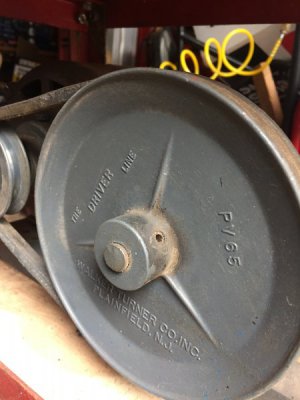
The countershaft setup on this lathe is unlike anything I’ve seen online of this model so I’m assuming it’s either homemade or a very early model.
 
Can anyone identify this countershaft setup? I’m assuming homemade.

2A8725F6-47BB-469B-AAB9-167E325A7661.jpeg

25940552-BB0C-4A08-931B-D96349193636.jpeg
 
Unfortunately, no. In the 1930's, Atlas made a Jack Shaft somewhat similar to this but they seem to have always used 4-step pulleys on both wood and metal lathes that they made. A supposed selling point (because it is mentioned in one of their ads) was that theirs had a mounting bolt pattern that matched some of the motor base mounting patterns. According to the ad, you could mount it in place of the motor on "many lathes". The mounting bolt pattern of this one is unlike the patterns of any motors then or now. So my guess would be that it's a generic jack shaft made by someone other than Atlas.
 
How do I determine the speed of my lathe with this setup?
 
You haven't shown a top view of the lathe with the countershaft and motor mounted and with the belts in place so we don't know how the 3-step pulley lines up with the 4-step spindle pulley. But the general equation for this case where "P" means "Pulley", "CS" means Countershaft, "*" means "times" or "Multiplied By", "/" means "Divided By", "S" means "Spindle", "1" is the large countershaft pulley, "2" is the in-use step of the CS step pulley and "( )" means to perform the "/" operation between "(" and ")" first before performing the "*" operations.

S-RPM = M-RPM * (M-P-Dia / CS-P1-Dia) * (CS-P2-Dia / S-P-Dia).

Note that the pulley diameters used should be the pitch diameters, not the outside diameters. For an approximation of the pitch diameters, subtract the nominal belt size (probably either 3/8" or 1/2") from the pulley outside diameter. And hopefully there are no typos in the above.
 
Back
Top