[Documentation] Zip-cut Vertical Mill - My First Mill + Resto (lots Of Pictures)

MasaAMD

Registered
Registered
Joined
Jan 1, 2017
Messages
31
Hello everyone!

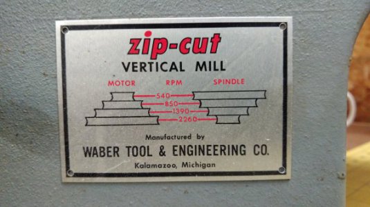
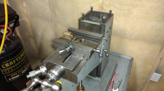
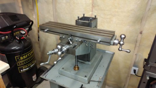
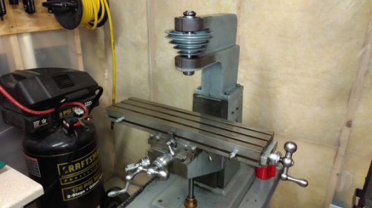
I just recently acquired my first vertical mill in a local estate sale. The mill is a Zip-Cut Vertical Mill made by Waber Tool & Engineering Co. Not sure of the vintage or how many of these were produced, but myself and ZIPandGRIZZ seem to own the only two out there. There is little to no information about these mills online and unfortunately I was unable to locate any documentation at the sale. The story I received was that this mill was previously owned by Western Michigan University, then put into storage, then ultimately acquired and brought home by one of the engineering professors.

The mill looks to be in great condition and I was surprised to even find cosmoline still covering many of the surfaces! Really the only wear can be attributed to storage in a slightly damp basement and a few superficial dings on the table.

Anyway lets get into it!

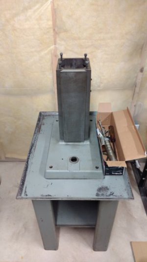
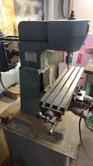
This is how I originally found it. Lots of sawdust from being in a basement wood shop.
IMG_20161217_094912.jpg

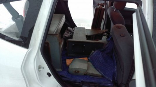
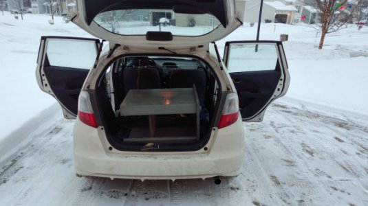
After a good hour of breaking it down and pulling it out of the basement in pieces I was finally able to get it all into my car and home. Boy this thing was heavy!!
IMG_20161217_165300.jpg
IMG_20161217_165323.jpg

Time to really dive in and see how they put this guy together. Yup, that's the original cosmoline! And check out the flaked gib
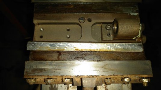
IMG_20161231_172504.jpg

Table off, and that's not rust! More cosmoline!
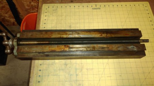
IMG_20161231_172524.jpg

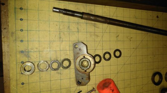
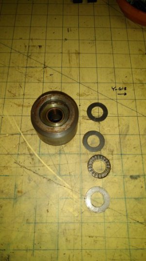
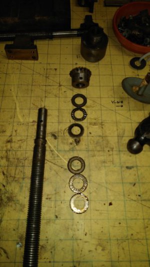
Closeup of the handle and dial. The leadscrew rides in a bronze bushing with two roller thrust bearings (more details on this later).
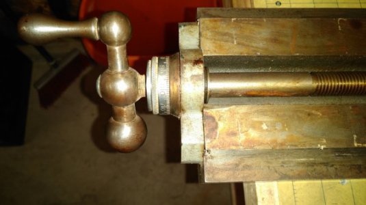
IMG_20161231_172537.jpg

So here's a little step by step for tearing down one of these leadscrews. First remove the handle retaining screw and tap off the handle. The dial is held in place by a setscrew.
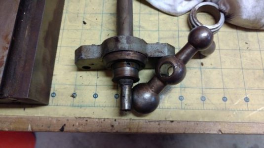
IMG_20161231_174633.jpg

Watch out for that tiny woodruff key!
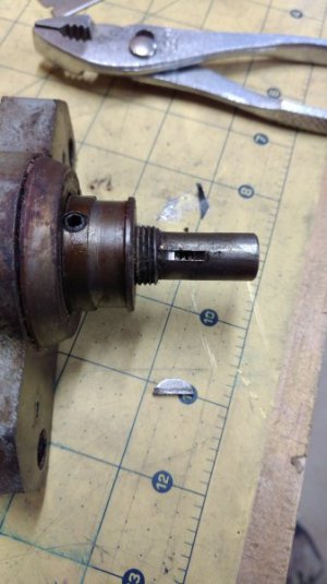
IMG_20161231_174752.jpg

Loosen the setscrew (I removed it at first, don't lose the tiny brass pad) on the bearing retainer and unscrew from the leadscrew.
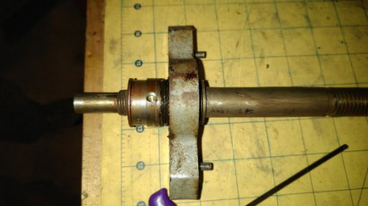
IMG_20161231_174958.jpg

Disassembled
IMG_20161231_175454.jpg

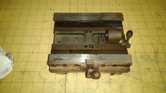
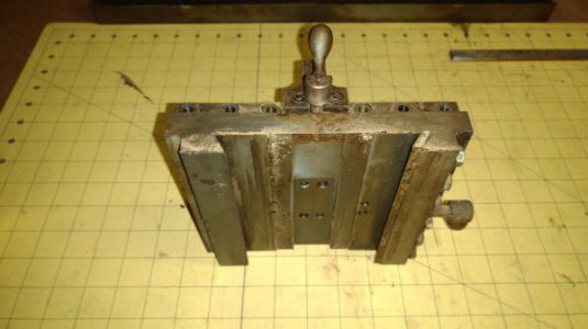
Time to remove the saddle! A couple of bolts and it can be slid off.
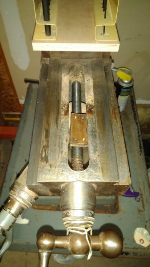
IMG_20161231_180544.jpg

And more of that protective sawdust
IMG_20161231_180557.jpg
IMG_20161231_180605.jpg

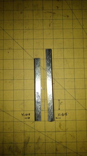
Gibs
IMG_20161231_180846.jpg

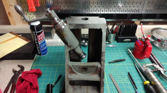
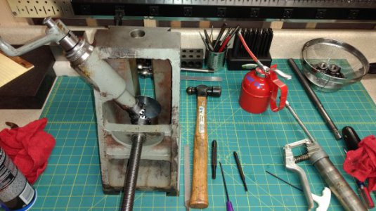
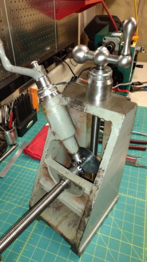
Time to remove the knee! And a closer look. Nice touch with the conic gear "umbrella"!
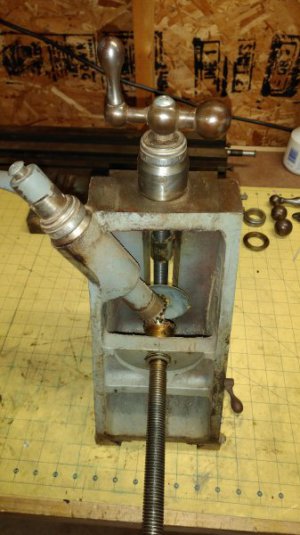
IMG_20161231_182551.jpg
IMG_20161231_182557.jpg

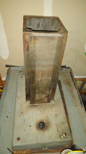
Here's the column. Little bit of surface rust and cosmoline but nothing a razor and some elbow grease can't take care of!
IMG_20161231_182613.jpg

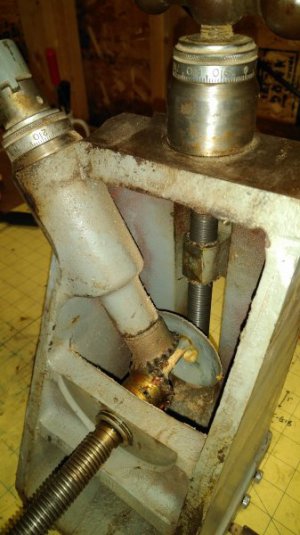
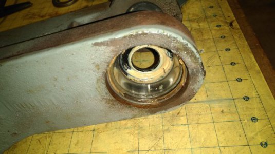
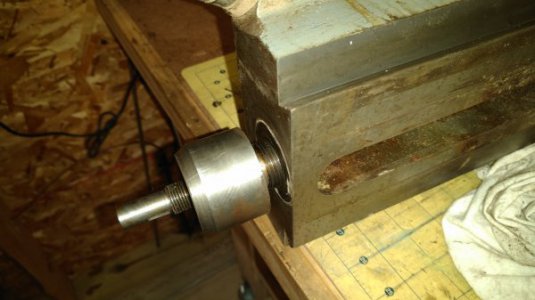
Time to break down the Y-axis. Note the threaded bushing retainer.
IMG_20161231_185506.jpg
IMG_20161231_185608.jpg
IMG_20161231_185709.jpg

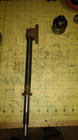
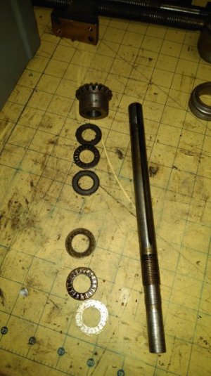
And here are the knee screws. Check out that oil grove!
IMG_20161231_193618.jpg
IMG_20161231_191503.jpg

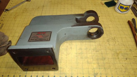
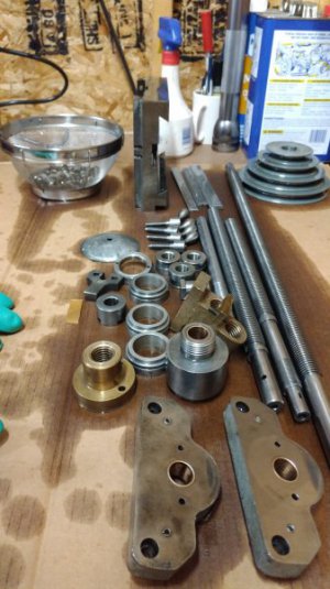
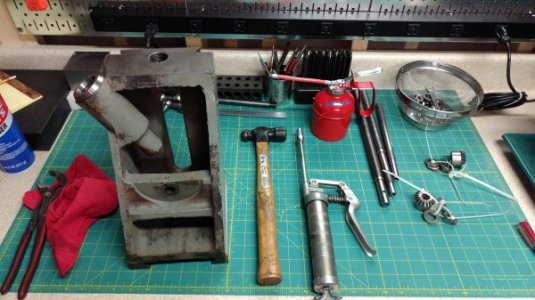
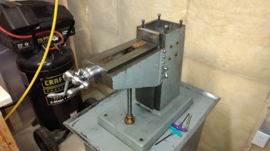
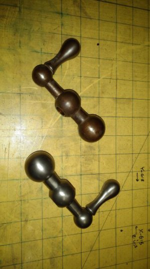
That's all for now. Next up, time to clean! Hope you all enjoyed the pictures and breakdown. Expect more to come! And here's a little teaser!
IMG_20170101_193115.jpg
 
Congrats on the pick up and welcome to the forum! Never seen that mill before, looks to be a well built machine. Also looks like it'd be pretty easy to make a riser block if you ever need a little more room between the spindle and table.

Bruce
 
Simple and solid, always a good combo. What type of tooling/collets does does it take? Welcome to the forum. Mike
 
Very neat and rare as hen's teeth I'm sure- is it made here or asia?
Mark S.
 
Thanks everyone! Made right here in Kalamazoo, Michigan USA. The spindle is MT 2, so the sky's the limit and it also allows me to share tooling between my mill and lathe.
IMG_20170102_175122.jpg


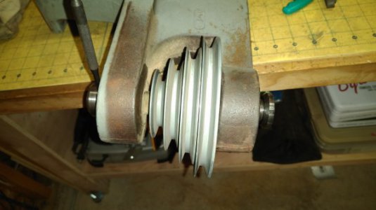
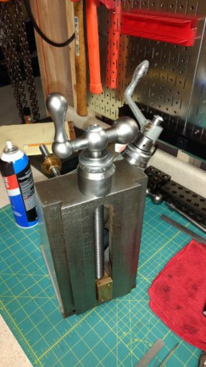
Alright, time for some more progress! So today I am working on the head. Let's see how to break down this spindle. Nice touch lip seals all around (better picture further down)!
IMG_20170102_180636.jpg

Prepping the spindle for the press
IMG_20170102_182518.jpg

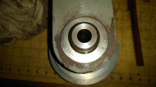
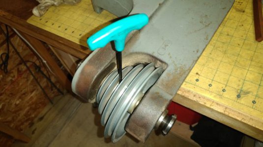
Remember to loosen the setscrew on the pulley
IMG_20170102_182531.jpg

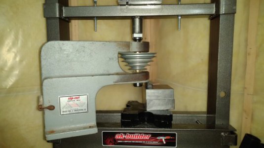
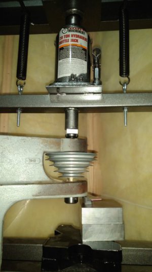
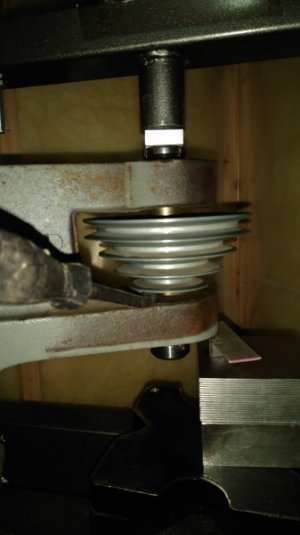
Time to press! Here's the setup, just fits in the 20 ton
IMG_20170102_185007.jpg
IMG_20170102_185013.jpg
IMG_20170102_185020.jpg

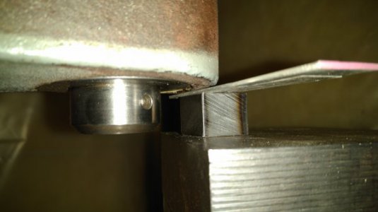
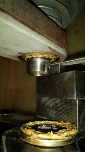
Its always a good sign when things start moving like they should! Don't forget to keep the pulley sliding too. A little heat and some gentile prying on the boss got it going in the right direction.
IMG_20170102_185322.jpg

Bottom lip seal out! Nice and waxy! Going to repack with MolyGraph EP grease and reuse the seals (surprisingly the rubber is still soft!).
IMG_20170102_185816.jpg

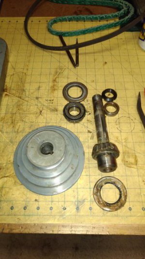
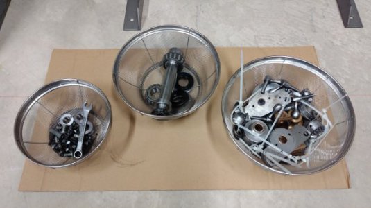
Alright everything's out and ready to soak! BTW those are Timkin tapered roller bearings.
IMG_20170102_191956.jpg

Outer race and inner lip seals
IMG_20170102_192002.jpg
IMG_20170102_192010.jpg

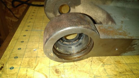
Head all cleaned up! Going to leave the outer races pressed in
IMG_20170102_194700.jpg

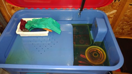
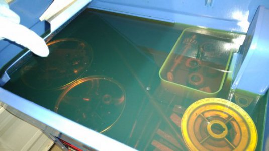
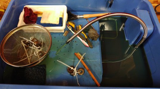
Time for a diesel soak! That's about half a mill in there!
IMG_20170102_210204.jpg
IMG_20170102_210224.jpg

That's all for tonight! More scrubbing tomorrow!

And when I'm getting ready to put everything back together I'll compile a little spec sheet with bearing and seal numbers, dimensions, travel lengths and things like that for anyone who's interested.
 
I saw that the Waber company is still in business, they make drill stands which a safecracker would love. No mills anymore tho. :(
Mark S.
 
Yeah, I saw that they are still in business as well. Might pay them a little visit when I get this thing together to see if they have any documentation archived away. Those drill stands do look like a safe cracker's dream though! Haha

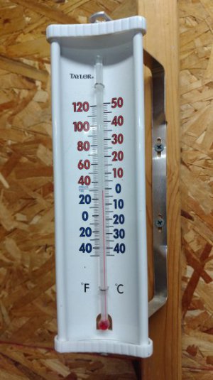
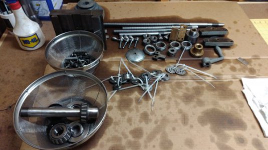
Alright progress time! So after a good soak to loosen everything up its time to start scrubbing. A little nippy in the garage tonight...

IMG_20170104_184507.jpg

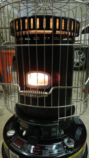
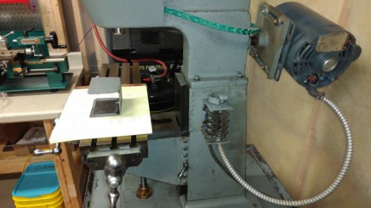
Time to fire up the heater! BTW for anyone with an unheated shop I highly recommend one of these Kerosene heaters. Lots of heat and plenty of burn time.
IMG_20170104_191815.jpg

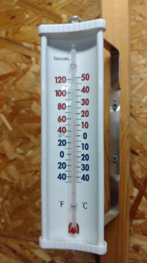
Much better!
IMG_20170104_213756.jpg

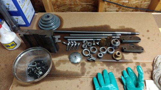
Anyway, back on topic! Freshly scrubbed and (brass) wire wheeled.
IMG_20170104_213809.jpg
IMG_20170104_213903.jpg

Roller thrust bearings cleaned up nicely. Prior to install all bearings will get a heavy dose of brake clean and a good blast of compressed air to remove all traces of old grease and dirt.
IMG_20170104_213816.jpg

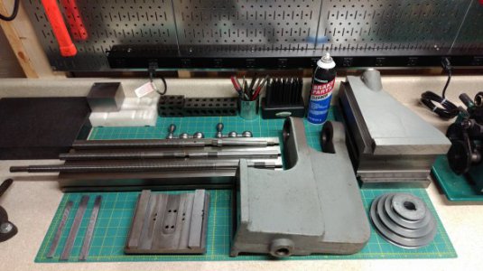
All scrubbed! Time to dry everything off and bring it downstairs to the shop.
IMG_20170104_223507.jpg

Next update, assembly!
IMG_20170104_235634.jpg
IMG_20170104_235643.jpg
IMG_20170104_235653.jpg
 
Assembly time! Let's build this thing!

First up, the knee. I'll start by installing the horizontal crank screw then move onto the vertical. Conic gears are pinned in place using a roll pin. Thrust bearings are packed with CRC EP MolyGraph grease. Backlash is adjusted by tightening or loosening the leadscrew nut. A little bump past hand tight gives a nice smooth rotation without too much resistance.
IMG_20170105_194051.jpg
IMG_20170105_200427.jpg
IMG_20170105_201856.jpg

Time for Y-axis lead screw. The bushing block screws into the front of the knee and its the same process for taking up the backlash. Don't forget to screw the brass nut on before sliding the leadscrew into the knee casting.
IMG_20170105_205300.jpg
IMG_20170105_205314.jpg

Slid back onto the column.
IMG_20170105_212751.jpg

Saddle time. Don't forget to screw in the X-axis lock and bolt up stop plate before sliding the saddle onto the knee. If you forgot like I did, you will have to pull it all back off and then screw it in (handle hits the knee). Ultimately I ran out of travel on the X-axis locking screw when I tried to clock it's position without having the table installed. Temporary fix until I can turn a new one is a simple socket cap screw.
IMG_20170105_221957.jpg

Table installed. Also I switched the crank handle to the right hand side instead of the left. Conveniently there is about a 1/2" stub on the opposite bushing block. Perfect spot for a DIY power feed in the future.
IMG_20170106_005050.jpg

Unfortunately I didn't take many picture of the head rebuild. Everything went together fairly smooth. Bearings were packed with MolyGraph and I used the spindle nut to to set the bearings and preload.
IMG_20170106_005939.jpg

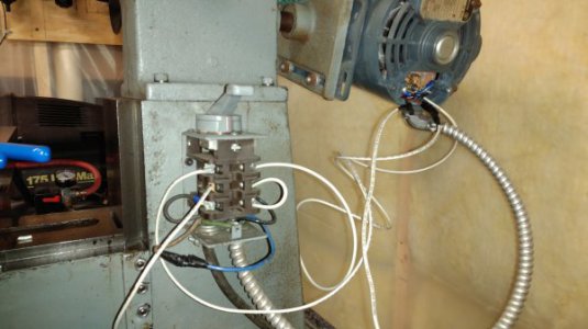
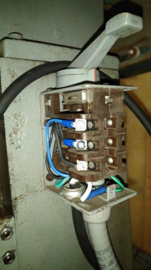
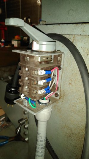
Alright, time to jump into this wiring mess. I should have taken picture before installing new terminal ends but I have no idea how the previous owner didn't shock himself or trip the breaker with the amount of bare and stray wire strands in the drum switch. Here it is cleaned up and wired in its original configuration. (And of course it doesn't function correctly, does not reverse and sounds terrible when operating the switch in that direction)
IMG_20170106_235029.jpg

That's it for tonight. I'll be migrating the wiring troubleshooting to the electrical subforum. This drum switch/motor combo has me a little stumped. When I get it all figured out I'll post the wiring diagram up here.
 
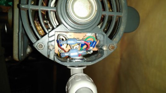
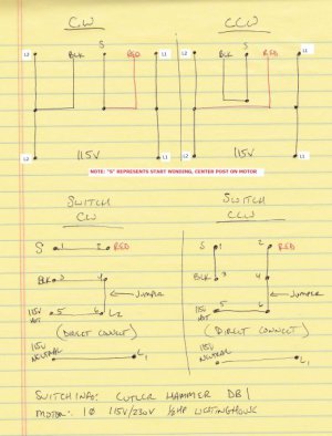
So two steps forward and one step back on the electrical. Good news is I was able to figure out the wiring for the drum switch and get the motor to spin in both directions. Not so great news, the motor was wired for 230v so it had no power at all... And in trying to switch it over to 115v I've opened up a whole another can of worms.

Anyway here's the progress so far. First things first here is the wiring diagram. (This is the revised version. There were errors on the previous diagram.)
wiring v2.jpg

Test setup. Will look much better after a run to the hardware store.
IMG_20170107_224244.jpg

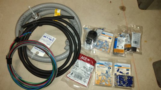
Back with supplies. Time to wire it up right.
IMG_20170107_224616.jpg

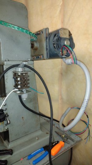
Running the wires
IMG_20170107_233338.jpg

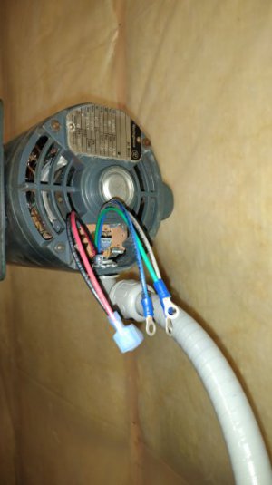
Motor-side terminals done.
IMG_20170107_234646.jpg
IMG_20170107_235656.jpg

Drum switch done.
IMG_20170108_002024.jpg IMG_20170108_002033.jpg

That's it for tonight. Now I just need to figure out how to get this motor wired up properly for 115v
 
Last edited:
Back
Top