Z-axis Cnc Conversion

JimDawson

Global Moderator
Staff member
H-M Lifetime Diamond Member
Joined
Feb 8, 2014
Messages
11,176
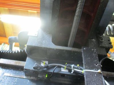
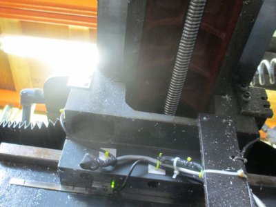
I am adding a Z-axis to my 2-axis Eagle CNC mill. This is a full upgrade project with a new computer, new software, and all new controls. I just installed the Z-axis scale today. These are 1 micron (0.000039 inch) resolution scales. That means I can position pretty close, that doesn't mean I can machine to that tolerance, it just means I have a fighting chance of getting kind of close.

All of the new magnetic scales are mounted on the machine now and are tied into the computer. The only thing left at this point is to build the Z-axis drive hardware. I removed all of the original quill feed hardware, don't think I'll be needing it any longer.

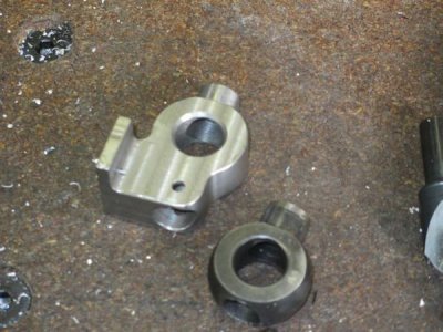
First I made a new quill stop to be able to mount the reader head. I wanted it pretty strong so I made it out of 4140.
quillstop.jpg


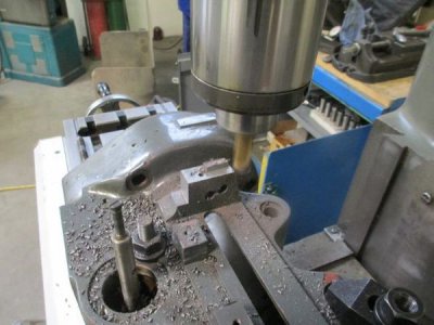
Then I had to do a little machining on the head to clear the scale mount and new quill stop. I also flattened out the upper stop face to I could later mount the quill counter balance. I did this on my old mill that I sold to my friends at ADX Portland, they were kind enough to let me use it again.
removingstep.jpg

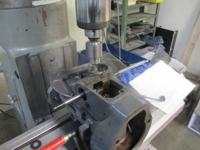
While I was there I also located, drilled and tapped the mounting holes for the Z-axis drive hardware. I have the head clamped to an angle plate for this operation.
zmountholes.jpg


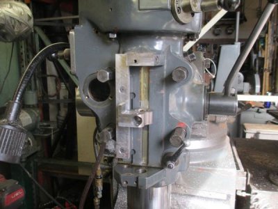
The next step was to mount the mag strip backing plate, I used the original scale mounting holes, but retapped them for 10-24 because was the size flat head screws I had in the drawer.
zscale3.jpg

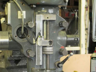
Here is the almost finished Z-scale install, I still need to make a proper cover for the big hole there. With all the quill feed hardware removed, it makes a nice junction box for the connection. The cable from the reader head tracks nicely right beside the head clamp bolts without binding. The magnetic strips are attached with a 3M 'it ain't never gonna come loose tape', pretty much resistant to every known coolant and oil.
zscale6.jpg

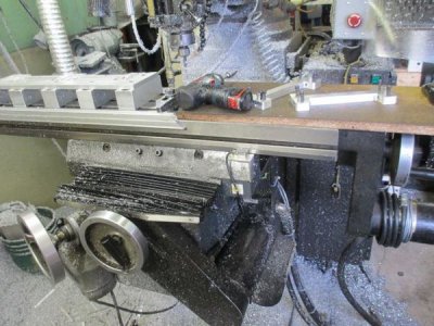
The X-axis scale. I installed the X and Y axis scales in November, right in the middle of a job after the the original encoders failed.
xscale.jpg

The Y-scale.
yscale.jpg

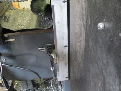
The K-scale. Originally there was a glass scale on the knee axis. I used the original mounting hardware for that to mount the new magnetic scale. The knee will not be under computer control, but does show on the DRO screen.
kscale.jpg

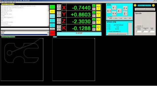
The DC CNC controller screen. (EDIT: This is a really old version of my software)
screenshotsmall.jpg

yscale.jpg
 
Last edited:
Continuing on:

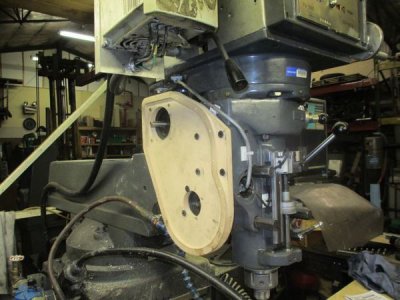
This is the mock up of the gear case. I built this to check fit and clearance, and to make sure the G-Code was correct. I made this out of 3/4 MDF. The real gear case will be made from 2" thick aluminum

gcmounted1.jpg

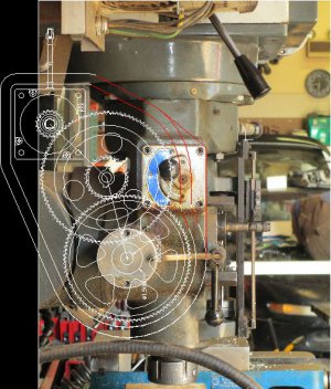
This is the concept I am working on

Mill%20Head%20Drawing%20Side%20View.jpg

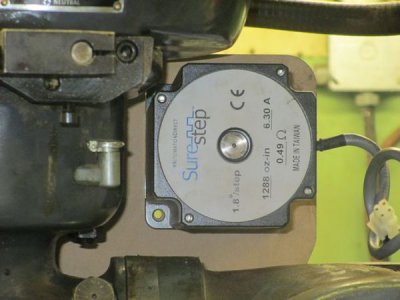
The stepper motor fits!! I was a bit worried about the clearance

stepmotor2.jpg

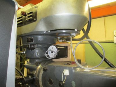
Another view

stepmotor.jpg


More Later!!
 
Last edited:
Looks like a good design. Will you be able to disengage the gearbox if you want to use the machine manually?
 
Looks like a good design. Will you be able to disengage the gearbox if you want to use the machine manually?


Yes, there will be a lever on the gear case that operates a cam that will disengage the intermediate gear from the bull gear on the quill shaft. The gear train will stay engaged with the motor, so there is only one gear to line up when you engage it again. A little wiggle of the quill lever will align it again.
 
Update:

I have done quite a bit of work since the last time I posted here.


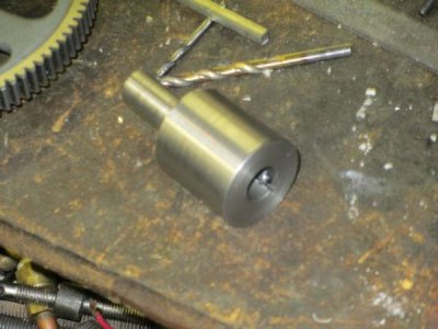
The quill shaft adapter. This is made in 2 pieces. The quill shaft is 15mm and the gear bore is 5/8 so I needed an adapter to tie everything together, I also needed a 5mm keyway through the bore. First I made the cylinder with the 15mm bore then threaded the shaft end 1 inch - 32 about 3/4 deep. Then I made the gear shaft to match.

quillshaftadapter.jpg

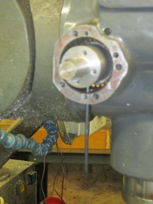
Sorry for the poor picture quality. The quill adapter is held in place with two 1/4-20 setscrews. I drilled and tapped two 1/4-20 holes in the mill head, in line with the set screws, so I could reach in with an Allen wrench to tighten the set screws. I'll install set screws in the access holes to plug them on final assembly.
quillshaftadapter1.jpg

The bull gear is free to turn on the shaft. It drive the quill through four 10-24 soft machine screws. If I did my calculations correctly these will shear at about 125% of design torque. The quill shaft should take about 200% of the design torque'
bullgearassy.jpg


The gear case is now complete.

Finishing the cover

gearcasecover1.jpg


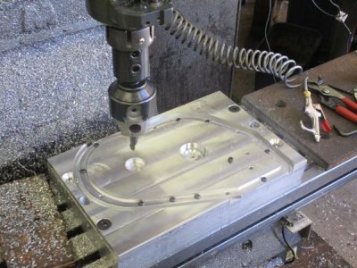
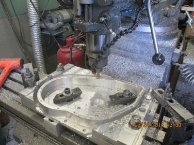
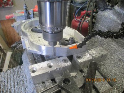
Converting a perfectly good block of aluminum into chips

gearcase1.jpg


Finishing Pass
gearcasefinalpass.jpg

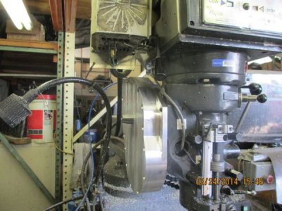
The gear case in place, the fit looks good
gearcaseinstall1.jpg


The cover installed. I am going to change the design of the disengage cam a bit, it sticks out way too far. I may use the existing feed engage/disengage lever since it is no longer used anyway and needs to be removed to install the spindle tach hardware.
gearcaseinstall2.jpg

The next step is to polish the gearcase and send it out for anodizing. I'm thinking a pretty blue.

I need to install the travel limits next. Actually only one limit switch is needed. I am using the original up/down feed stop hardware to drive the limit switch. I have to do this to allow use of the existing quill stop. If I used full travel limits, and forget to screw the quill stop all the way down, then that would not be a good thing. The limit switch will be installed behind the scale mount plate, and will be actuated by the original feed stop push rod.

After that, the air counter balance will be installed, you can see the attaching hardware already installed just above the quill stop. There will be a cable attached to that assembly that will run to a remote mounted air cylinder.


More later......
 
Last edited:
Question:

What did you do to eliminate the play from backlash at the mating point of the quill gear and the rack milled in the gear? It seems that this would allow vertical Z movement which would result in an uneven surface?

Thanks,

Lynn
 
Question:

What did you do to eliminate the play from backlash at the mating point of the quill gear and the rack milled in the gear? It seems that this would allow vertical Z movement which would result in an uneven surface?

Thanks,

Lynn


You are absolutely correct Lynn. What is not installed yet is the counter balance cylinder. Some of the hardware for this is addressed in this thread and a few others I have posted. The quill return spring will take up the backlash in the gear train to some degree, but won't do a thing for the rack & pinion backlash.

The counter balance cylinder will exert about 50 lbs of up force on the quill, at least this will be my starting point. I'll post more on this when I get the hardware built and installed. The counter balance will be controlled by the computer and a manual switch for auto or manual operation.

Edit: I should also note that when not z-axis profiling, the quill lock will be locked and under computer control also.
 
Last edited:
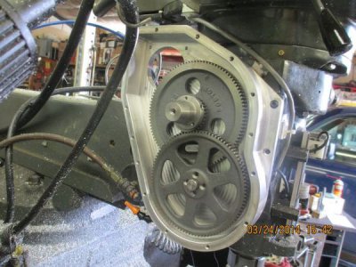
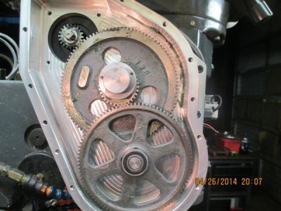
I got the gear box mounted and dialed in today, finally. Been busy with other stuff. I also have the Z-axis drive electronics under computer control now. I spent about 2 hours running the gears in with the quill shaft drive screws removed so I could run the motor continuous at full speed (equivalent to about 450 IPM, I think I'm going to limit this to about 60 IPM max). The bull gear drives the quill shaft through 4 soft screws that should shear under an overload condition.

I haven't actually run the quill up and down yet because I don't have the travel limit installed yet. Things could get ugly in a hurry without a travel limit if I did something stupid. The parts for the travel limit should be here in a couple of days.

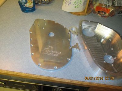
Nice clean gear case parts right out of the dishwasher

dishwasher.jpg


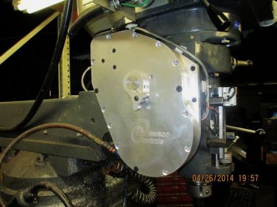
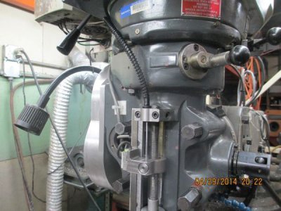
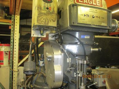
The gear case installed. I decided to send this out for anodizing later, after I make sure no modifications are required.

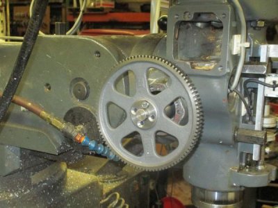
The wires hanging out to the right are for the travel limit. To disengage the quill from the drive for manual operation, loosen the knob and rotate to the other hole (to the right of the camshaft). The 3 cap screws, upper left, hold the motor shaft outboard support bearing housing.

camlever.jpg

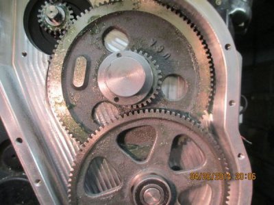
The drive engaged. I was happy to find that there is virtually no backlash in the gear train. The cam operating lever is adjustable to compensate for gear wear if needed.

gearsengaged.jpg


Gears disengaged.

Note that the intermediate gear never disengages from the motor pinion, so to re-engage you only have to wiggle the quill handle a bit. I need to get some real open gear grease, the stuff I pulled off of my shelf just kind of squeezed out.

gearsdisengaged.jpg

The next step is to fab the parts for the quill counter balance air-spring, this will take all of the backlash out of the system, including the quill rack and pinion backlash. Going to work on that tomorrow.

More Later...
 
The Z-axis CNC Conversion is alive!!:victory:


The last steps were the air spring quill counter balance and the Z-Axis limit switch.

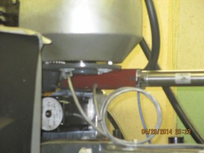
The cable is a somewhat shortened brake cable for a Yamaha Banshee. The other end is attached to the air cylinder assembly.

counterbal1.jpg

The air cylinder assembly is bolted to the top of the gear box.

counterbal2.jpg

The square tube is a chunk of 2" steel tubing I had laying around, it will look better when it gets painted.

The air cylinder regulator is T'ed to a portable air tank from HF, that way I have a large volume of air, relative to the cylinder volume, to keep the pressure constant at about 30 PSI. When I get the rest of the controls installed, the counter balance will be operated by a switch and the computer when the Z-axis is engaged.

counterbal3.jpg

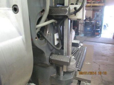
The limit switch uses the original quill feed trip out hardware. The switch is buried in the plunger housing to protect it. Easily serviceable, just remove one set screw and it comes right out. You can just see the top of it behind the scale cable.

zlimit1.jpg


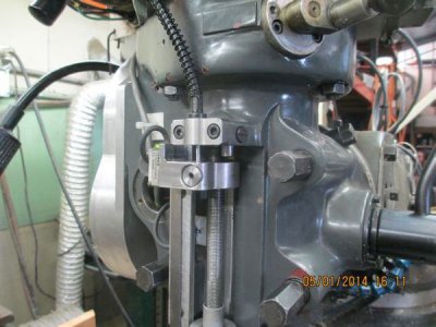
The limit actuates both top and bottom via the quill feed trip out. The pushing down on the adjustable stop will trip the switch as well as the upper rod trip out. (picture center just above the quill stop.

zlimit2.jpg

In this conversion I don't think I lost any quill travel at all. And the adjustable stop still works just like it always did for manual operation.


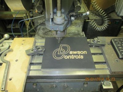
Here is the first full 3 axis cut on this machine (OK, 2 1/2 axis, but who's counting). I pushed the GO button and the mill did the rest. Next of course will be a full 3D profile to make sure it actually works as planned. Just a scrap piece of MDF with a quick coat of flat black.

firstcut.jpg

Next is the quill lock, the new control panel and the rest of the controls.

Go to the top of the thread to see the whole process
 
Back
Top