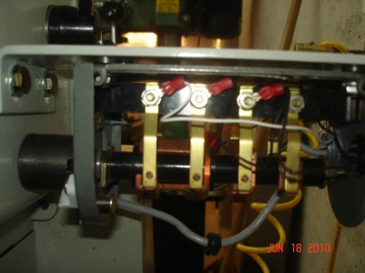
Wiring reverse-off-forward switch to vfd

Livewirefabworks

Registered
Registered
Joined
Sep 7, 2011
Messages
8
I have a 1945 sheldon lathe that I wired a teco vfd to to convert from single to three phase. I would like to us the origanal switch to control the drive functions. Have a couple of ideas on how to do this but was wondering how you guys have done it.

Thanks,
Andy
 
Wire the existing switch with the incoming 1 phase to turn the VFD on/off - its that simple. Instead of wiring to turn the motor, lamp, grinder, etc on/off, you'll be switching the VFD. You'll use the 3 phase out of the VFD to do on/off/rev switching.
 
[quote author=Pacer link=topic=3691]
Wire the existing switch with the incoming 1 phase to turn the VFD on/off - its that simple. Instead of wiring to turn the motor, lamp, grinder, etc on/off, you'll be switching the VFD. You'll use the 3 phase out of the VFD to do on/off/rev switching.
[/quote]

I don't see how that will help the OP? He is not trying to turn it ON and OFF...
 
Last edited:
[quote author=Livewirefabworks link=topic=3691.msg26949#msg26949 date=1316887629]
I have a 1945 sheldon lathe that I wired a teco vfd to to convert from single to three phase. I would like to us the origanal switch to control the drive functions. Have a couple of ideas on how to do this but was wondering how you guys have done it.

Thanks,
Andy
[/quote]

Andy, here is what I did:

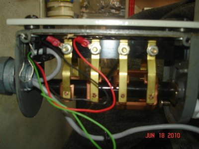
Strip all the wiring from the drum switch, you won't need it anymore...power to the VFD can be controlled via a two pole switch-just like a regular light switch but made for 240v so it breaks both legs.

The wiring from the VFD to the motor is direct, so no switch is used or wanted there.

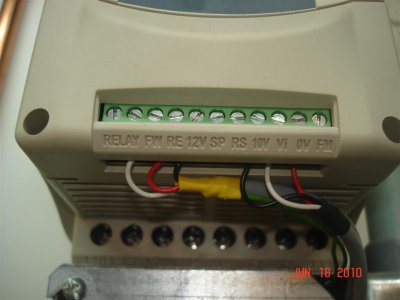
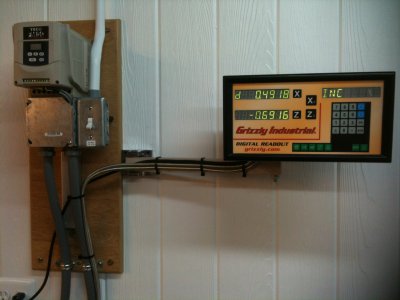
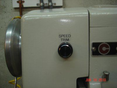
Now, using an Ohm-meter identify what contact are "made" when switching the drum switch to FWD and REV, then use small wiring to connect them to the external control terminal on the VFD. I also added a remote POT so I can adjust the speed without reaching to the VFD.

DSC09538 (Large).JPG IMG_1051.jpg DSC09536 (Large).JPG DSC09535.jpg DSC09537.jpg
 
Last edited by a moderator:
Hey Kennyd,

That was what I had in mind almost to the t. I have the Teco jnev-202-h1 vfd and the manual is kind of hard for me to figure out what ports are what. I wish they were as clear as yours. So is your remote the 24v output?
 
[quote author=Livewirefabworks link=topic=3691.msg26995#msg26995 date=1316964776]
So is your remote the 24v output?
[/quote]

It's 12v I think but who cares...you are just making contact closures to control the FWD and REV functions. You only need small gauge (#16 or even #18) wire to do it.
 
Last edited:
I just looked at the manual: http://www.tecowestinghouse.com/Manuals/EV_Installation.pdf

It looks like you wire from Terminal #8 (Common) to Terminals #4 and 5 (S1 and S2) shown on page 6. So you need three wires...

Then, you must define the function of S1 and S2 as FWD and REV in the setup program, see the chart on page 17, F11 and F12

A 10K pot can be added as well for speed/frequency control, shown on page 6 also.

Clear as mud?
 
[quote author=Livewirefabworks link=topic=3691.msg27033#msg27033 date=1316985821]
Thanks Kennyd. I know what I am doing Monday when I get home from work.
[/quote]

You are quite welcome...

I would do the programming first, then just short accrosed the terminals to test things before you start running wires. I assume you have the motor and feed all hooked up already?
 
Yeah I do just to test the vfd but I am going to run new conduit and rewire the whole system. Jumping it does sound good as a test.
 
Back
Top