Wiring a Peerless motor to a furnas drum switch to a 1/2 HP Peerless motor on my Logan 825

joebiplane

Active User
H-M Supporter Gold Member
Joined
Nov 22, 2010
Messages
371
Hi guys & Gals
I bought a Logan 825 about 6 Months ago and it ran fine at the sellers house. he disassembled it for me to take home and removed the upright pole that holds the FURNAS motor reversing switch and disconnected it from the junction box on the peerless 1/2 hp 110-230 volt motor I now have a cord with a plug on one end to plug the lathe in but it is not wired to the motor or drum switch....I also have a Furnas drum assy that is wired to the drum but not to the motor or plug in cord .. the motor has a junction box that contains contains 3 wires with metal bands labled T-1 T-4 and C-1 also have a cluster of wires all wired together and capped off labled T-2, T-3 C-2 I know irt was running on 110 when I bought it as I ran it and tested it out:thinking:

Might anyone have a wiring diagram that could help me get it properly wired ??? Or a suggestion how to get it done
I have erbuilt the machine but I am just terrible with electric....always have been and I guess I always will be:whiteflag:

Thanks
Joe biplane
 
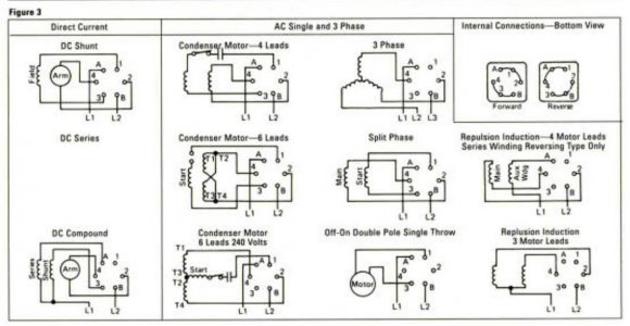
I'm not sure where I got this diagram from but IIRC it is for some Furnas switch. I assume you have a capacitor start motor. If yes I think you want to wire it using the diagram "Condenser Motor - 4 Leads". L1 and L2 are the two wires white and black from your wall plug. Your C1 from motor to #1 on switch, T1 to #2 on the switch and T4 to #4 on the switch. (If it works backwards try swaping T1 & T4). If you don't already have a green ground wire from the wall plug you should add one, attached to the body of the switch and from there to the motor frame.

EDIT: Please see comments in posts below, I suspect there may be a problem with the text in red above!

FurnasA14Switch.jpg
 
Last edited:
Wait, back the truck up!!!

Something is bugging me about this. You said the motor was originally wired for 110 but the 3 wires (T2,T3,C2) connected together would make me think the motor was wired for 220. Does the motor have a wire diagram for 110 vs 220 wiring? Check inside the cover. If yes please post a picture.
 
Mr. CluelessNube;
You are 100% on track. He needs to use the diagram on the middle left of your drawing. This shows (In a kinda confusing way) the two run windings in parallel. The drawing that "SEEMS" more obvious puts the windings in series for 240v operation. If they would just LABEL them as 120v and 240v life would be so much easier. All motors made after about 1948 are wired and built the same as they are built by all manufacturers to a standard. These standards are set by NEMA, National Electrical Manufacturers Association.

These standards are kinda fun to read about when, how and why they were made. In a nutshell. Most all of it started after 1900 when standards for machining came about. WWI sped up the process and WWII finalized it. They are mostly standard in the US and Briton. With the rest of the world using a metric version. All this was so plane and tank parts would interchange. Or until SAE (Society of Automotive Engineers) started in the US even simple fasteners had no standard except from the blacksmith who made them. How would you like to have two 1/2" x 1" bolts, one for a Ford and one for a Chevy, that won't interchange!

Fun stuff!

Not to hijack or get to far OT but how our standards came to be is an interesting bit of history. I found myself chasing links all day on a rainy Sunday and found the information quite intriguing. Amazing what a couple of little ol' World Wars will do to get everything in sync.
 
Re: Wait, back the truck up!!!

Something is bugging me about this. You said the motor was originally wired for 110 but the 3 wires (T2,T3,C2) connected together would make me think the motor was wired for 220. Does the motor have a wire diagram for 110 vs 220 wiring? Check inside the cover. If yes please post a picture.

When I bought the machine it had a 110 plug attached to the wiring and was plugged into a 110 outlet... When started is seemed to take about two seconds to spool up to speed. That seemed odd to me but I never had a cabinet model lathe with the under drive belt system that Logan uses.
Now after reading your kind replies I am wondering if it might be wired for 220 and hence slower to spool up on 110 v. Is this a possibility????? As I have stated I know almost nothing about electric

Thanks
Joe larsen
 
I am wondering if it might be wired for 220 and hence slower to spool up on 110 v. Is this a possibility?????

The short answer is YUP! I purchased a Walker Turner drill press that was wired for 220 with a 110 plug, it ran but started slow. When I took the motor apart to change the bearings and replace the old power cord I found that it was miss wired. If I remember correctly a motor wired incorrectly that way will only develop 1/4 rated power.
 
Once again CluelessNewB you speak the truth. Your numbers are a little off but we are talking calculated theory and I was never good at it anyway. My experience is when wired to high voltage and subjected to low voltage is they will barely even run, let alone do any work.

I bet you thought that 'ol Walker Turner was a gutless piece of sh*t! I think my old Walker Turner is one of the Cadillacs of the shop. Wired correctly of course!

Keep that SWARF airborne!
 
I bet you thought that 'ol Walker Turner was a gutless piece of sh*t!

Actually I never even used the WT900 hooked up like that, Since it was my second drill press I was in no rush to use it and immediately took it all apart for paint, cleaning and wiring and bearings. When I went to disconnect the crunchy old power cord I noticed it was not wired correctly. I also replaced the starting cap since I had the motor apart anyway. And yes those old WT drill presses are fine machines, it works great now. I now have both a WT1200 and a WT900. (and yet another WT900 waiting to be restored).
 
Back
Top