- Joined
- May 20, 2014
- Messages
- 30
Any yesteryear guys around that still remember about white metal casting ?
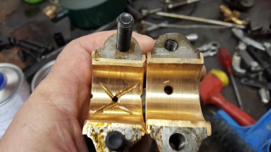
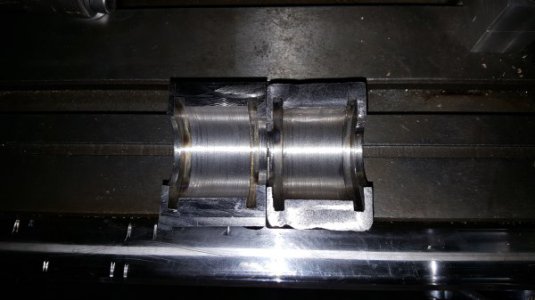
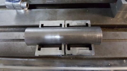
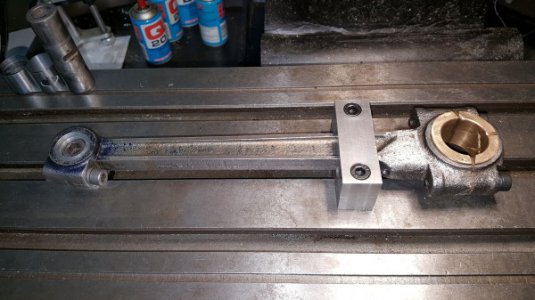
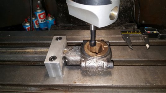
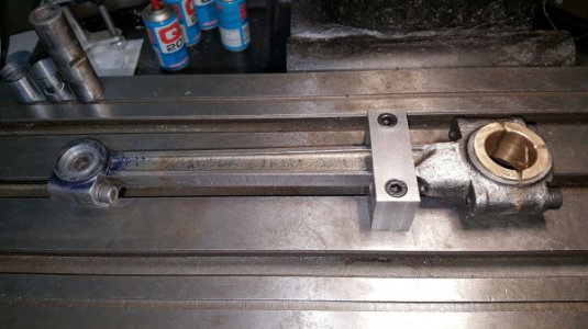
I am about to try my hand on white metal casting on bearings for an old 1930's throttle governed engine. I have machined the crank, but the bearings made by previous owner are a bit oval so I align bore it. I want to cast white metal to get everything up to standard again ;-) As an amateur machinist/engine builder so many question comes to mind while working on this project.
What is the ideal thickness I should push for on the white metal after casting and align boring?
How big "gap" should I try for between crank and white metal to allow oil to lubricate and conrod to freely turn on crank ?
If I can get info on the gap for lubrication, the ideal thickness of the white metal, only then I can do my final cut on the bearing face The engine only runs at about 600 rpm max so in my mind I think maybe I can get away with a few thousands here and there but it would be nice to know what is ideal tolerance.
Any ideas would be highly appreciated.
I am about to try my hand on white metal casting on bearings for an old 1930's throttle governed engine. I have machined the crank, but the bearings made by previous owner are a bit oval so I align bore it. I want to cast white metal to get everything up to standard again ;-) As an amateur machinist/engine builder so many question comes to mind while working on this project.
What is the ideal thickness I should push for on the white metal after casting and align boring?
How big "gap" should I try for between crank and white metal to allow oil to lubricate and conrod to freely turn on crank ?
If I can get info on the gap for lubrication, the ideal thickness of the white metal, only then I can do my final cut on the bearing face
Any ideas would be highly appreciated.


