What’s the best way to determine/measure a bolt circle?

OK I'll ask the obvious.....does your mill DRO have a bolt circle function? It's an even number of holes, so the holes opposite one another are the diameter of the bolt pattern. Snug fitting pins, and measure the distance between the outside of the pins and subtract the diameter of one of the pins= bolt circle diameter. Of course this is all out the window if the bolt holes aren't equally spaced( but this can be checked by pinning and measuring adjacent holes pair by pair to confirm they're equal ), or you happen to have a DRO that doesn't do bolt circles!
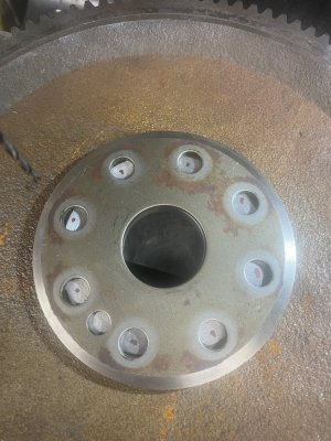
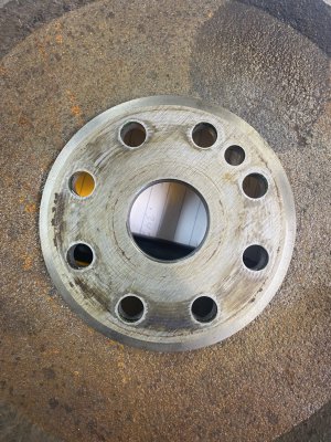
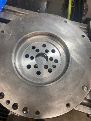
Yes, I have a DRO with the bolt circle option. I ran through it yesterday. I think I have it perfect
I hope
 
I would have done it without the pins.

Take inside diameter of hole and zero out the caliper.
Use inside dimension part of the caliper to measure the hole spacing going to both holes outside diameter.

Easy peasy.
It seems there are many ways to determine the bolt circle.
 
Using the DRO bolt circle function I made a test run.
Looks promising.
 

Attachments

  • IMG_1692.jpeg
    IMG_1692.jpeg
    417.1 KB · Views: 8
Yuasa makes a good one too. Almost any little job can justify another big expenditure.
I have a Railmikes (sp) out of Jersey down here that is nice . For BCD's you can't beat them . 8" adjust true chuck , horizontal/vertical set up . Years ago when I sold out I dumped my Hartford dividing head . Kicking myself in the ass for letting it go but at that point I was never getting back into machining . I have a 24 plate in the Railmikes which does many BCDs and I use a sine bar to split the difference when needed . :encourage:
 
For bolt patterns, I'd much rather press a few buttons on a DRO, than wrestle a 75#+ rotary table on/off the mill table.
 
For bolt patterns, I'd much rather press a few buttons on a DRO, than wrestle a 75#+ rotary table on/off the mill table.
When you have 20 parts , I wouldn't think so . :grin:
 
When you have 20 parts , I wouldn't think so . :grin:
For sure, that's a completely different story. For this one off, those holes would have been done via DRO in less time than it takes to bolt down a rotary, indicate it to the spindle, and then the part. And if a home shop machine is too small to have both the vise and rotary table( or super spacer, indexer, etc ) on the table at the same time, then that means moving the vise and re-trammimg it when it's moved it back. It takes a minimum 48"+ table to be able to do that, IMO. I tried having my 6" Kurt and a 10" rotary on my Lagun with a 9"x42" table, and the work envelopes for either one was pretty skimpy in the X axis.
 
Came out great.
Thanks for the help.
A special thanks to my friend Dave, aka mmcmdl.
 

Attachments

  • IMG_1693.jpeg
    IMG_1693.jpeg
    619.5 KB · Views: 5
  • IMG_1695.jpeg
    IMG_1695.jpeg
    363.6 KB · Views: 5
Looks good and the dimensions you sent are dead nuts . :encourage:
 
Engine flywheels can have odd bolt hole spacing so it only lines up one way.
This video helped me get my holes laid out for my chuck adapter with out a DRO
I wish I had a DRO though

I can only tell you it worked
 
Back
Top