- Joined
- May 7, 2014
- Messages
- 776
Yep.... Me again. Wow- tons of respect for you guys that do this everyday!
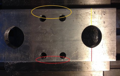
Issue: I'm onto my next CNC generated part and I've determined that my Y cuts seem off over .125? in the Y+ space (I think I have that right). I cut two parts w/o really noticing. bummer. I'm learning fast there.
From the pic, it cut in too far towards -Y and left a large offset then to the Y+ edge of the part.
I did part zero as:
Find X edge w/ my edge finder. (.2 wobbler) used .1 to get to wobbler center.
Find -Y edge. Went .1 back into -Y to center.
The 5/16 cutter sure looked centered to me.
I ran the dial indicator along the long edge of the part.... 0.0 +/- a thou. It was square.
after- I ran several Y direction tests w/ the magnet base and 1" dial indicator. It's dead on. 1.000 is recorded as 1.000
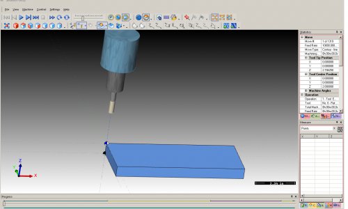
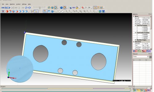
Could there be something wrong in the CAM post processor - even though it looks fine on the simulator? Or am I unsure where 0.0.0 should be when I do the wobbler and then put in the cutter in. I've included the two pics. 1 from the sim, 1 of the part. 0.0.0 of the sim cutter is where my physical cutter was too.
The dxf drawings were dead on square on both sides. CAD and then CAM all look OK?
I'm just wondering where to dig now? I'll try a few circles and a few test holes later or tomorrow.


