Vn No 10 Feed Components

Manderioli

Registered
Registered
Joined
Feb 7, 2016
Messages
172
Hello,

Does anyone have info on the components specifically for the belt drives to run the feed mechanism on a no 10?

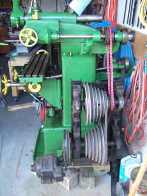
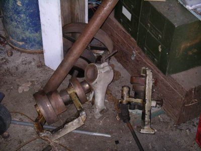
Attached is a photo of my machine without any of the mechanism. I would really like to use the feed without customizing brackets to run another electric motor.

Any info would be great.

I already have the blueprints to show the devices yet would like further info.

IMG_4043.jpg
 
Hello,

Does anyone have info on the components specifically for the belt drives to run the feed mechanism on a no 10?

Attached is a photo of my machine without any of the mechanism. I would really like to use the feed without customizing brackets to run another electric motor.

Any info would be great.

I already have the blueprints to show the devices yet would like further info.
Hi Neighbor,

I would very much like to see more photos of your machine.

I don't have a lot of information on the No. 10. There's a 4 page PDF file that has erection plans and a 2 page brochure, which it sounds like you already have. Beyond that, all I've got are a few photos of another machine.

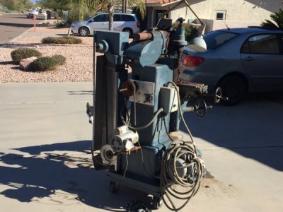
This photo shows the telescoping shaft that connects to the table and the mechanism on the back of the machine:
VN10-9182 drive.jpg

This one shows part of the rear bracket and the shift mechanism. I'm not sure what the shifter does; it may allow you to reverse the feed direction.
VN10-9182 DSCF1153.jpg

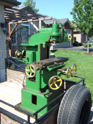
The feed mechanism appears very similar to that used on the No. 1/2. In fact, it looks like the No. 10 is an updated version of the No. 1/2.

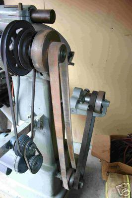
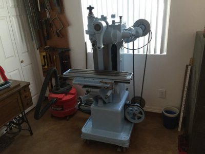
Here's a photo that shows how the flat-belt drive for the feed mechanism works:
Irby Jones 3.jpg
Note that there are two pulleys on the back end of the horizontal drive shaft on the side of the ram. A long belt runs from one of them to an idler with 5 pulleys on the base of the machine. The long belt can be used in either of the two front positions of the idler pulley, giving two drive ratios. A second, shorter belt runs from one of the three remaining idler pulleys up to one of three corresponding pulleys on the mechanism at the center, rear of the column (which drives the telescoping shaft). The two belts and the various pulley combinations allow for a total of 6 different feed drive ratios.

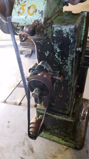
Here's another photo showing the idler and the mechanism on the back:
VN1_2 sn7132 - 20161114_105729.jpg

This photo shows the underside of the mechanism from the rear of the column (on the right):
VN1_2 sn8142 VN62.JPG

Unfortunately, you seem to be missing the idler pulleys and the mechanism from the back of the column as well as the telescoping shaft.

I hope this helps.
 
Thank you Cal for the photos.

My machine originally came with a separate motor and make shift brackets, bearings, etc to drive the feed system.

What is the mechanism called that bolts to the feed shaft and has the 3 stepped pulley? I guess not many come up for sale. Any suggestions on who could have the components I desire?

So the belts drive the pulleys, which then turns gears similar to the feed gear mechanism on a lathe so you can have two directions of travel?

IMG_1279 (1).jpg

IMG_2227 (1).jpg
 
I don't know what the correct name is for the mechanism on the back. We could call it the feed select mechanism (FSM). I think the chances of you finding one for sale are about zero. If you could find a No. 1/2 that someone is parting out, maybe, but 1/2s are rare as hen's teeth. The feed system from a No. 12 could probably be adapted to work, but it uses a separate drive motor.

I'm sure you could make something similar to the original system, but you'd be mostly working from photos. I would use V-belts or automotive serpentine belts if I were going to do that.

Here’s how the rest of the feed system works: The two belts and 3 stacked pulleys drive the FSM. It has a gear train that I think is just used to reverse the feed direction (there doesn't appear to be any other way to reverse the feed). The cone pulleys on the back of the FSM turn whenever the spindle is turning. I don't know if the FSM has a neutral position that can disengage the feed there or not. If not, its output, which drives the rear end of the telescoping shaft (via a universal joint), is always turning as well.

The other end of the telescoping drive shaft has another universal joint which drives a worm gear that rides in casting which is hinged at the rear. When the feed is engaged, the worm is brought into contact with a worm-wheel that directly drives a sleeve in the top of the saddle, with the nut for the table feed screw. When the feed is engaged, the nut rotates and pulls the feed screw through the nut, moving the table.

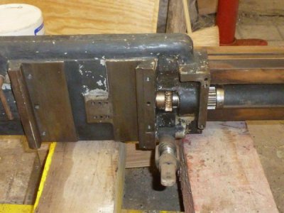
Here's a photo of the bottom of a No. 1/2 saddle:
VN1_2 sn8142 P1020294.JPG
The saddle is siting on it's rear surface. You can see the worm gear casting tilted out from the saddle, pointing towards the camera. Immediately above it is the bronze worm-wheel. The worm casting is normally rotated up so that the worm gear engages the worm wheel. On the right end of the shaft is the gear that's driven by the right hand-wheel.

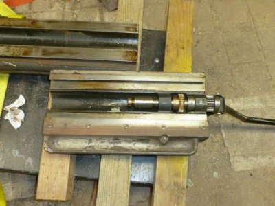
Here's a photo of the top of the saddle:
VN1_2 sn8142 P1020297.JPG
You can see the tube (hollow shaft) that moves the table. About in the middle of the saddle, on the left end of the shaft, is the nut and backlash adjuster. The bronze worm-wheel and drive gear can be seen to the right. The leadscrew runs through the nut and tube. The feed mechanism moves the table by rotating and pushing/pulling the leadscrew and thus the table.

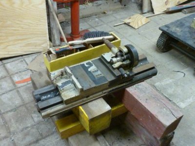
Here's another photo of the underside of the saddle, with the saddle resting on the table:
VN1_2 sn8142 P1020291.JPG
You're looking at the back of the saddle and table. On the right, the right angle drive for the right side handwheel is visible (it was removed in the first photo), with the shaft for the handwheel pointing away from the camera. The large round black thing on the right is the cover for the gear which drives the smaller gear shown in the previous two photos. You can see the stub end of the shaft that drives the worm gear peaking out from under the right angle drive. There's a universal joint that attaches to the shaft and in turn connects to the front end of the telescoping drive shaft.

I'm not sure how the lever that engages the feed by tilting the worm gear casting works. I don't have any good photos of it. Maybe you can figure out how that works and post some photos of it? As always, lots of good photos are greatly appreciated.
 
Back
Top