Verifying An Angle Plate

PatMiles

Active User
Registered
Joined
Sep 5, 2014
Messages
98
I have an angle plate that I want to verify the squareness and parallelism. Might any of the learned folks on this site care to tutor me on doing so? I figure that this might take some time and effort on my part (duh) so it will require a bit of time. Any help will be greatly appreciated.
Along the same lines, is there anybody that offers regrinding of an angle plate if needed?
Thanks,
Pat
 
Tom Lipton at OxTool did a You Tube video on measuring squareness.

It depends upon your level of tolerance but you could probably do a reasonable check with a tenths reading test indicator and a known good square like 2-4-6 block. I would set up a test indicator in the spindle of my mill and sweep the known good square to determine any deviation. This is essentially measuring the tram of the mill spindle. Clamp a reference edge to the table to ensure alignment to the same position each time. Replace the reference square with your angle plate and sweep it. You should be able to detect a difference of a tenth or so over the height of the plate. Parallelism could be checked with an appropriate mike or with an indicator sweeping a face while the opposite face is on a surface plate.
 
Hi Pat,

I remember one of the books in the Dave Gingery series had details on how he made some small angle plates for mounting things to the lathe faceplate.
http://gingerybooks.com/
http://gingerybookstore.com/

Likely either the lathe book or the accessories book...maybe the mill book?. He had a method where he bolted one to the lathe faceplate and a second one to the first. That gave the ability to face-off the second one. There was a system of adding spacers and operations such that you ended up with a matched pair of guaranteed square angle plates. I believe he made them out of angle iron.

The exact steps elude me, but I know I could find them again. Let me know if you want me to dig it up and give some better details.

I don't know if yours would fit on a lathe faceplate (I do not know the size you are dealing with), but the concept should be similar.
If you had two and could find a way to mount them, you could put an indicator on them give them a manual spin and maybe get an idea how good/bad they are.

-brino
 
The most universally accepted method is with a cylinder square and squareness gage.


Sent from my iPad using Tapatalk
 
The most universally accepted method is with a cylinder square and squareness gage.

Anyone onboard who can explain how to use these instruments? Although it sometimes frustrates me I love accuracy!
 
A cylinder square is a relatively easy gage to make because it can be made on a lathe in a single setup. The cylindrical surface is turned and the end faced. As long as you are not turning a taper (verify by miking the cylinder) and your lathe is not facing convex, you should have a perfect square relationship between the face and the cylindrical surface. You can purposely face a concave surface or cut a slight recess, leaving a thin raised ring on the perimeter of the face to prevent possible rocking. Due to symmetry, a cylinder made in this way is square to the face no matter where you approach it which is a useful feature.

I have not used a squareness gage but watched Tom Lipton (Ox Tool) use one in one of his Monday Night Meatloaf You Tube videos. Others with actual experience may want to chime in.
A squareness gage is constructed similar to a height gage with a flat base and a vertical beam. An indicator on the vertical beam is capable of sweeping a vertical surface. The base has a reference edge that you bring your test piece up to. You can adjust/calibrate the squareness gage to read true for a cylindrical square. You the put your test piece in place of the square to verify its squareness or measure its deviation. A surface plate is used to ensure a reproducible flat for the square, the gage, and the test piece to rest on.
 
I should add that I would expect the a precision cylindrical square will ground rather than turned but the principle is the same. It is possible to make a precision square using only a micrometer to verify its accuracy. Additionally, it is fairly easy to verify the accuracy after the fact by rotating the square held to a reference edge (usually a Vee) and measuring runout.
 
Search the YouTube videos of "the tool and die guy" for "how to check a block for squareness". Here's the direct link:

All you need is a small surface plate, a surface gauge with a fine adjust, and a dial test indicator (tenths preferably but 0.001" graduations will still get you pretty square). You also need to radius the front of the surface gauge somehow.

Easy once you see how it's done.
--
Rex
What the "tool and die guy" is verifying is that the angles are the same. In order to use properly, you need to go a step further and mike top and bottom to determine that the two faces being compared are parallel or you need to use a known good square (e.g. the cylindrical square) to set it gage up. It also only works as shown if you have a block with parallel sides.
However a good 1-2-3 block or better, 2-4-6 block should be fairly close to square , squareness to a tenth per inch or better. You can easily mike the block to verify parallelism and check as demonstrated for equality of the angle, flipping it over to verify the same reading. Once you are satisfied your block is true, you can zero the indicator and check your test piece.
 
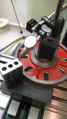
OK, here is a way to answer the OP's question with tools we have available.
1. Place an 8" faceplate from the lathe face down on a surface plate.
2. Place a magnetic base test indicator on the hub of the face plate and lock it down.
3. Adjust the position of the test indicator at the approximate height of the contact point of the tested object.
4. Adjust the test indicator to read zero when rocking a 1-2- 3 or 2-4-6 block around the circumference as per the video. Check the opposite side for variation. Flip the block end for end and note the difference. If they measurements are all the same to your desired accuracy, you're good to go. Otherwise, averaging the four readings is going to be fairly close the the "square" reading.
5. Place your test piece in position and repeat the measurement to determine its squareness.

Any plate will work for the base. The faceplate just has a convenient curved edge built in. Here is a picture of the setup. (Yeah, I know I need a bigger surface plate; it's on the list)
Squareness Meas .JPG
 
Back
Top