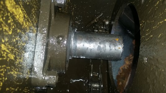
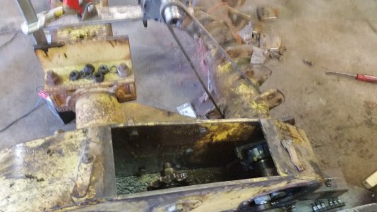
We have an implement known as a rock rake that had a sprocket ran lose for too long and finally the sprocket was wandering all over. At least by the time I was involved that was the state. After removal of the sprocket it seems a previous owner had welded the shaft up and ground it down by some means. If they did it by hand I am quite impressed as it was 0.030 out of round. The nominal diameter was 1.4375" (1-7/16") and it was down to 1.400 (ish) and I could still see weld beads. So I can only guess how far down it had been before we got it.
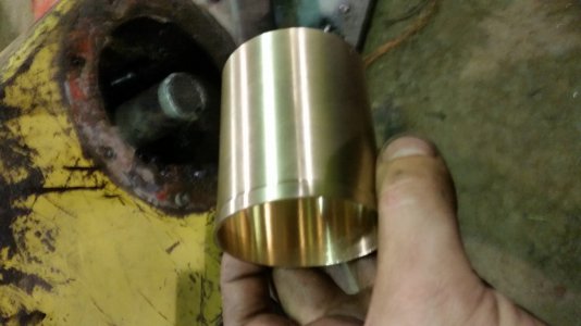
The bearing that supports the shaft had been run without a locking collar in place for so long the shaft was undersized 0.050" and a locking collar would not stay on the bearing shoulder. The first item of business was to make a bronze bushing that was heated and driven onto the shaft. The bushing had a thickness of 0.020 and was a trick to get on. When I turned the bushing I left a shoulder on it to place a tube against and drive with. With a new bearing in place and with a helper holding a propane rosebud to heat the bushing we drove it on and when it cooled we could not rotate it. I cannot really quantify beyond that how tight it was. We then cut off the driving shoulder.(similar to the process of a speedi-sleeve) I am still questioning if it will stay in place but so far after half a day of operation it is still there.
After this comes the bridgeport sacrilege.
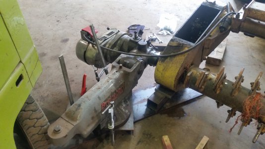
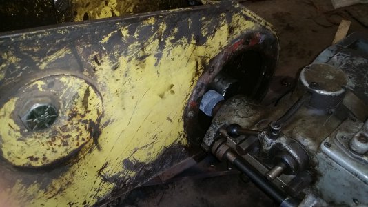
We decided to install a taper lock sprocket for their superior clamping power. Since the shaft was already close to 1.375 we decided to grind it in place. The shaft is welded to a tube that is 16 feet long that has rows of teeth and I didn't know of any lathes in the area that could handle such a creature. To do this we removed the turret of the bridgeport and attached it to c channels welded to a 1 inch steel plate that was resting under the rock rake. We also parked the forklift on the plate for good measure. Once in place and after half an hour of trying to indicate on a very worn shaft it was in place and with the head rotated 90 degrees we were ready to start. We used 2 inch diameter medium grit wheel in top cog on the bridge port and manually fed with the quill. This is a little under half speed for most grinding applications but it worked OK. My biggest concern was applying too much stress to the little 1/4" shank on the wheels. This is why I fed it manually so get some sense of feel how hard it was pushing.
We rotated the shaft using a sketchy looking arrangement that consisted of a DC gear motor turning a junk B series belt we had wrapped around the reel of the rock rake. The turned the shaft at about 40 RPM.
About a minute into the operation i stopped to check things out and do a bit of measuring and discovered the grinding wheel was getting hot. This seemed to be affecting the accuracy as I assume the wheel was expanding. (yeah I know funny to worry about accuracy with this setup). To counter this and keep the binder from degrading I sprayed water on the wheel once it cooled. From then on I had the three armed affair of holding the water spray can, runing the quill feed, and running the DC motor speed control. By this time I had no helper. One really nice thing about spraying water was it kept the grinding dust down. Once I had made a pass I would adjust the ram of the bridgeport to move it back 0.010" The last pass I made with a fine grit wheel. The spec for a taper lock is 0.000-0.002 under for this size and I left it at 0.001 under. The biggest challenge was after a couple passes measuring the diameter accurately to adjust the turret to keep it perpendicular to the axis of the shaft. The final diameter varied about 0.005 over 3.5 inches of ground area. This leaves some areas out of spec, but its quite a bit better than before and we had not trouble mounting the sprocket.
The keyway had been V shaped from the key rocking and I really could not come up with a good way to cut a new one so we cut a custom key with a taper that matched the shaft keyway. Once we assembled everything we added a couple of two piece shaft collars to help keep thrust in check. When the machine hits a large rock it tends to put a lot of thrust on the shaft.
I was rather surprised how well this operation worked. We'll see if it proves to be durable. I may find myself dragging the top half of the bridgeport around to more places.
A little note on the machine: The rock rake's job it to be drawn across a field with the reel rotating and engaging about 1-2 inches in the soil and hit rocks forward. The reel is angled about 30 degrees relative to the direction of travel so the rocks are thrown to the right and eventually end up in a narrow band next to the machine. Needless to say the drive line takes an incredible amount of abuse and shock loads. I've converted another one to hydraulic drive which has reduced the amount of driveline maintenance and I think this machine will get the same conversion when time permits


