Tool and cutter grinder build

I intend to have a little brass somewhere. I always try to add some brass accents to projects to give a little "bling" to them.:))

It's all about the bling. Everybody knows that including bling adds +/- 0.0003" precision/accuracy to anything we make. :thumbzup:

Mark
 
Mark, I am offering the following as a reference to potentially assist you and others building or wanting to build a tool grinder.

Yes, I know the text is in German, (I am a Kraut and can’t read it either, had enough trouble with English growing up). However the 3D CAD drawings and excellent photography coupled with superb craftsmanship makes the concepts understandable. This guy must be an Engineer. You won't believe the bling until seen!


What may be of assistance is the “Decal” method of applying degree markings (laser printed on tape), no ball handles but lots of Socket head cap screws and large hand knobs. The spindle / motor assembly is very good. I think if it were easily detached it could be mounted to double as a tool post grinder.

http://www.metallmodellbau.de/
Home page
http://www.metallmodellbau.de/MINI_BONELLE_1.php
First attempt at T & C Grinder
http://www.metallmodellbau.de/MINI_BONELLE_II.php
Rebuilt T & C Grinder
http://www.metallmodellbau.de/Eigenbau-Universalspindel.php
Spindle / Motor Assembly

During my search for technical advice on these T & C grinders, I found some info. answering my questions about zeroing datum’s etc. Will be sharing soon.

Enjoy!

Restorer

 
Oh boy...the light bulbs just went off in my head big time!

This probably isn't a new idea to some here, but it is to me. I was looking at the X/Y table and the tool head fixture that is mounted on it when wham! It hit me: I already have a perfectly good X/Y table, connected to a Z-axis column that has a head on it that will tilt from vertical to horizontal. It has R8 collets for holding the grinding wheels, and it even has a DRO on all three axis for controlled movements. All I need do is build the tool holding fixture mounted on the X/Y table!

I may have found another job for my little PM25... :think1:

beware of grit
 
Mark, I am offering the following as a reference to potentially assist you and others building or wanting to build a tool grinder.

Yes, I know the text is in German, (I am a Kraut and can’t read it either, had enough trouble with English growing up). However the 3D CAD drawings and excellent photography coupled with superb craftsmanship makes the concepts understandable. This guy must be an Engineer. You won't believe the bling until seen!


What may be of assistance is the “Decal” method of applying degree markings (laser printed on tape), no ball handles but lots of Socket head cap screws and large hand knobs. The spindle / motor assembly is very good. I think if it were easily detached it could be mounted to double as a tool post grinder.

http://www.metallmodellbau.de/
Home page
http://www.metallmodellbau.de/MINI_BONELLE_1.php
First attempt at T & C Grinder
http://www.metallmodellbau.de/MINI_BONELLE_II.php
Rebuilt T & C Grinder
http://www.metallmodellbau.de/Eigenbau-Universalspindel.php
Spindle / Motor Assembly

During my search for technical advice on these T & C grinders, I found some info. answering my questions about zeroing datum’s etc. Will be sharing soon.

Enjoy!

Restorer


Awwww... man, you had to show me that :veryscared:. I think I just redesigned my tool holder.:think1: Good thing I just started it . this gives me some great ideas to improve my tool holder, but I can't afford the brass that big so I can't have as much bling :rofl: . Well, keep me posted ,maybe we can find some more stuff to customize this project. :makingdecision:. And , yes,..... share that info :rubbinghands:


Thank you for sharing this. I appreciate it. Google translates the pages for me automatically.:))
 
Mark,

Todays installment was downloaded in Feb. of 2014, sorry I did not record the website.
The article is by: Harry J. Coch, for his rendition of the Quorn ( H.J.C. Quorn )

The cylinder grinding and surface grinding setups are awesome.

Using taper pins to establish zero and levels to set axis's horizontal are helpful.

I will have to study the setup technique in part #4 as I didn't get it yet.

View attachment FabedQuornTCArticle.pdf

Tomorrow I plan on posting part 3 of 3, a motor suggestion.

Stay tuned!

Restorer
 
Mark,

Todays installment was downloaded in Feb. of 2014, sorry I did not record the website.
The article is by: Harry J. Coch, for his rendition of the Quorn ( H.J.C. Quorn )

The cylinder grinding and surface grinding setups are awesome.

Using taper pins to establish zero and levels to set axis's horizontal are helpful.

I will have to study the setup technique in part #4 as I didn't get it yet.

View attachment 94179

Tomorrow I plan on posting part 3 of 3, a motor suggestion.

Stay tuned!

Restorer


Thank you, I had seen this article before and gotten some good ideas from it. I look forward to the next one
 
Got the spindle for the work head roughed out today.

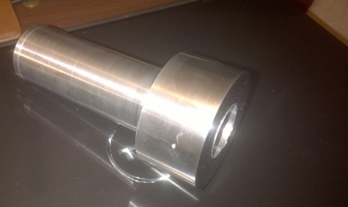
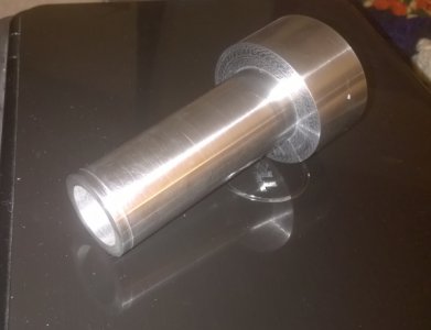
roughed out spindle 2.jpg The spindle for the work head is finished on the outside , but the inside still has to be machined for the 5C collet. I don't have any of those collets so I will finish it as soon as I get one.
roughed out spindle.jpg The spindle is 1.500" where it goes in the work head and 2.250" on the large end where the collet will go in. I did not have a piece of 2 1/4" steel bar to turn the spindle from so , I stole a 2 1/2" diameter x 2" long piece I was saving for my 4" rotary table project (Now I have to replace it to finish that project). I cut a 5" long piece of 2" diameter CRS For the spindle body. I threaded the end 2"-20 and bored out the 2 1/2" piece and threaded it 2"-20. I smeared the threads of both pieces with Locktite bearing mount and screw them together tight. ( this was about a class 3 thread). It will never come apart. I chucked it up and machined my spindle. I t came out perfect so far. I polished it up to a mirror finish.
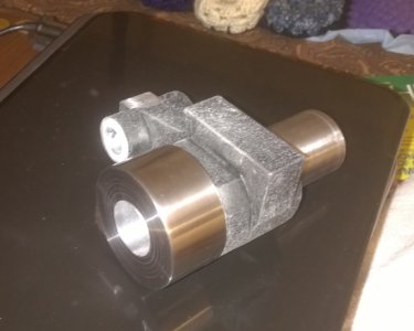
work head and spidle.jpg The tool holder body is aluminum and I think it is going to be a problem. I honed the bore to a mirror finish also and the two fit together great.
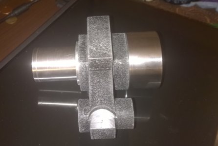
work head and spindle 2.jpg The problem is every time a piece of any dust gets in that bore, the aluminum galls and jams up the spindle. I polish it again and it is fine as long as no dust gets in it. This is a grinder..... can you say GRIT! I think this part may need to be steel. That chaps my a** because I got 16 hours carving that body out on the lathe and mill. Oh well, that's the way it goes. I may have to make it over from steel.

roughed out spindle 2.jpg roughed out spindle.jpg work head and spidle.jpg work head and spindle 2.jpg
 
Last edited by a moderator:
Can you press a steel sleeve into the tool holder body? Just a suggestion.
 
Back
Top