Tig Foot Pedal Potentiometer Value Question

maker of things

Hermit
Registered
Joined
Jul 23, 2014
Messages
347
I ordered a new pedal for my tig welder but didn't think to check the pot value. The pedal that came with my machine is 23k ohm but the new pedal is 47K ohm. I didn't check it until after I tried using it. The only problem I encountered is it seems to travel through the whole 200 amps in a small portion of the pedal's travel. Does that make sense for the difference in pot value to give that result?
 
I ordered a new pedal for my tig welder but didn't think to check the pot value. The pedal that came with my machine is 23k ohm but the new pedal is 47K ohm. I didn't check it until after I tried using it. The only problem I encountered is it seems to travel through the whole 200 amps in a small portion of the pedal's travel. Does that make sense for the difference in pot value to give that result?
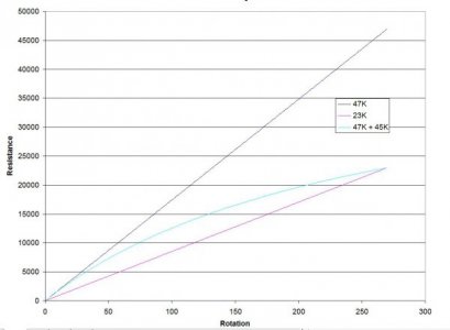
I am not familiar with your wiring but it is possible to change the effective resistance of a potentiometer. A 45K fixed resistor connected across the wiper and a fixed lug will alter the resistance to the range you need. The response is not linear but the deviation should be acceptable.Pot Range.JPG
 
If I am reading the graph properly, it indicates that the reason I get less travel with the foot pedal is that the resistance reaches the value the welder expects as full amperage much sooner. My old pedal has two pots to limit the max amperage (pedal bypasses the machine control). Adding another pot to the circuit will achieve similar results to the resistor but give me the ability to limit max amperage?

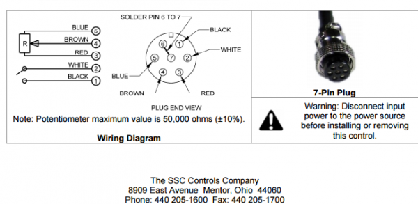
this is the diagram from ssc's website
upload_2016-5-10_9-18-51.png
 
There can be some variations depending upon how your potentiometer is used. A potentiometer can be used as a simple variable resistor (rheostat) or as a voltage divider. If pin 4 is connected to either pin 3 or pin 6 or if either pin 3 or 6 is not connected to external circuitry, it is a rheostat. If pins 3,4, & 6 are connected to external circuitry, it could be used as a voltage divider but not necessarily.

A clue is the statement of 50 Kohm maximum. The implication is that there is an external resistance involved.

If used as a rheostat, the graph above would apply. You would still need to know whether to connect the 45K resistor from pin 4 to pin 3 or to pin 6 which would be determined by the rest of the circuitry. I can't see that you would do any harm by connecting it to the wrong pin; you just wouldn't get the response you are looking for.

If use as a voltage divider, an external resistor may be being used to limit the maximum (or minimum) voltage. For example if 10 volts were available to the current control circuit but 5 volts would provide maximum current, an external resistance of 50K would limit the maximum voltage from the divider to 50K/(50K + 50K) x 10 volts or 5 volts. Changing the potentiometer to 75K would give a maximum voltage from the potentiometer to 75K/(50K + 75K) x 10 volts or 6 volts. This would mean that you would reach full current at 5/6ths of the pot travel. Other values can make the changes more dramatic. In this case, I would probably place the 45K resistor across pins 3 & 6.

To really know what is going on, you would need to provide a more complete schematic. Otherwise it is a bunch of guesswork.
 
Agree with everything RJ has said. One factor also is the type of taper the pot has. It's probably safe to assume it has the same type of taper as the OEM, but depending on the rest of the circuit configuration it doesn't have to be. Also you might want to know "which direction" it is operating. Is pedal down max resistance, or min? Again, I would imagine that most common TIG power supplies are basically the same, but there are so many ways to skin that cat it's scary.
 
Yes, I could see it not doing much until the last 1/3 or so of the pedal.
Here's an explanation of why. Typically a pedal pot is connected with 3 wires, ground, some fixed DC voltage between 5 and 12 volts and the wiper that varies between 0 volts (ground) and the 5 to 12 volt input. Now, there is circuit loading on the wire connected to the pot. So that lowers the voltage from the pot as well. The specific design calls for a 23K ohm pot to address the voltage curve from the wiper and the circuit load in the machine. SO lets say that the DC voltage was at 10 volts. It may not be but the math is easier. With the 23K pot and the circuit load at 50% pedal the voltage on the wiper would be 5 volts. When you put in a 47K pot in place of that the voltage at 50% is most likely only 1 volt. Maybe less. So the circuit is looking for 5 volts for 50% output and you are feeding it 1 volt, so you get 10% output. This throws off the entire curve of the voltage input that the machine expects. When you get up to 3/4 or so pedal you finally hit 5 volts and 50% output. Then you have all the rest between there and 100% which will still be at full pedal.

So I would send it back or get the right pot and put it in the pedal. It will work MUCH better.
 
Well I screwed that up. I took my resistance reading between pins 3&5 (red and blue) at the end of the cable. I failed to consider that the secondary pot on the factory pedal was turned part way.
I am going to start over.
1) are those the correct points to measure to evaluate the value of the pot?
1b) I am assuming those wires are connected to the ends of the resistor element (I'm reading from wikipedia so don't think I have a clue what I'm talking about).
 
When I turn the secondary pot on the factory pedal to it's lowest setting, the pedal reads around 50k so I guess the new pedal is the correct value must just not be linear in it's adjustment. It seems my larger problem is when any pedal is plugged in the main amp control is bypassed. The factory pedal has the secondary pot to limit the max amps, guess I'll just keep using the factory pedal for now.
 
Back
Top