- Joined
- Jun 12, 2014
- Messages
- 4,806
I have always found lathe chuck and collet stops somewhat lacking and difficult to use, especially with 5C and ER collet chucks. The 5C stop that I previously used, screwed into the back of the collet and stop slide mechanism was a piece of round stock held in place with an Allan set screw. So no fine (vernier) adjust and no way to set it relative to the spindle with the collet in the chuck. Depending on how hard the 5C collet was pulled in, it would change the distance relative to the spindle. I recently made an ER40 lathe collet chuck, and have not seen any chuck stop systems for it either. I have seen one through the spindle chuck stop made by Accu-Stop, but kind of clunky in that it uses an expanding mandrel spindle lock as has no fine vernier adjustment once it is locked. It also costs over $400, I think I will pass on that one.
I wanted to design a stop system that could be used in various capacities with different chucks, that would have both a course and fine stop adjust, and would fit a wide range of diameter stock. Since I use a spindle spider, I figured I could use the spider bolts to lock the body of the stop in place, and then use a fine pitch threaded rod for the vernier adjust. My spindle internal diameter on my PM 1340GT measures 1.59", so I chose some 1.75" x 7" 6061 for the stop body, I turned most of the length down to the spindle diameter except for an end flange (~3/4") and knurled the flange. I then center bored the stop body with an 11/16 drill, and drilled a 3/4" hole to 5". I then internally threaded the 11/16" bored end to 3/4"-20 UNEF. Once threaded, I parted off 1/2" of the flange to create a flange lock ring. I chamfer both the edges before parting it off. The stop body was then put in an indexer and I milled four channels at 90 degree intervals, each one 0.25" wide by 0.075" deep. These channels line up with the spider bolt holes, the brass tips of the spider bolts slide in these channels so the slot's length set the sliding limit and any deformation form tightening the spider bolts is in the channels not on the body.
The stop bar is 3/4" 6061 round stock, in the raw form it is somewhat irregular and the diameter was closer to 0.755". I turned the bar down to 0.749" and then cut a 3/4"-20 male thread about 7" on one end, the other end was tapped with a 1/4" female thread to accept various sized screw in steel tip stops. A cap is needed for the end of the threaded bar to be able to turn the bar for the fine verneir adjustment. The cap is 1" 6061 rod, knurled 1", center drilled the bar stock with a 11/16 drill to 1/2", and then blind threaded the female thread in the cap. Since I use the proximity stop system, I use the internal thread cutter to cut an ending grove within 0.001" of the cap wall, then proceeded to cut the thread. The major diameter is ~0.75, the minor ~0.69, so several passes at 0.01" with a total depth of just over 0.06". I use the cross slide for setting the cutter depth, so the stop position remains the same. Pretty much pushing my internal threading bar insert to its maximum thread depth limit. I did order a 3/4"-20 tap, but at the end of the day I didn't need it. Might have been handy when cutting the 2" 3/4"-20 internal thread on the stop body, this was also at the maximum length of my internal threading bar.
Since the stop bar is supported on the spider end but not the chuck end, you need to add a support ring for the bar that sits at the chuck end. So turned some 6061 ring so it has an OD of 1.59", ID 3/4" and width of 1" chamfered the edges so it slides smoothly into the spindle. I use a set screw to hold it in place, the position is set so that the ring face is even with the end of the headstock spindle with the stop at its maximum stop extension at the chuck end. Steel stop tips were cut from drill rod turned to an OD of 0.749", then two smaller diameter extensions are 0.499"x1.5" and 0.249"x1.5". I turned the diameters slightly under as to not interfere with the clamping of 0.500" or 0.250" stock. Other size tips can also be fabricated. At a later date I plan to make some precession height plates that will fit between the chuck jaws and will be held in place by drawing back on the chuck stop bar which will hold the plate against the face of the chuck body. Royal sells a set of three of these for $300, a bit crazy.
Anyway, the stop bar slides into the chuck body and then is threaded through the remaining 1.5", the flange lock ring is then screwed on and finally the rod end cap. It stays locked in place, but at some point I may consider using a left hand Allan screw in the cap end to lock it on. Screw in the desired tip, slide it into the spider end so the grooved reliefs align with the spider bolt tips. I have a little over 4" of course adjustment in the spider and another 5" from the threaded bar. The tips also can be adjusted, so the 3/4" one is 0.500", the smaller ones are 1.75" from the rod end. Different length stop bars can also be used. The repeatability on my 5C collet holder is under 0.001", so that is good enough for me.
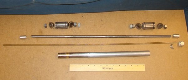
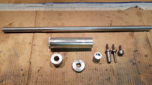
Stop rod with thread inserts, stop body, rod locking ring, stop rod end cap and spindle guide bushing for rod.
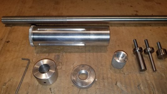
Assembled, ready to slide into the spindle.
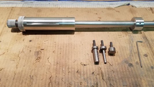
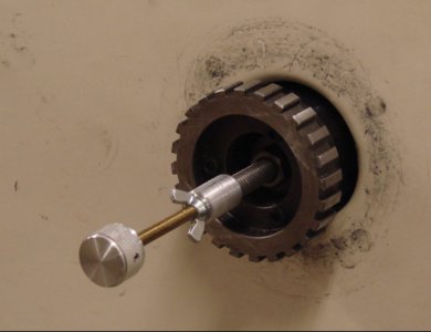
Inserted and aligned with spider bolts. Fully extended into the spindle.
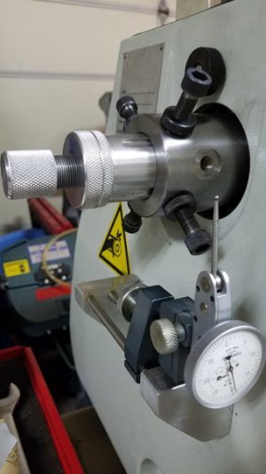
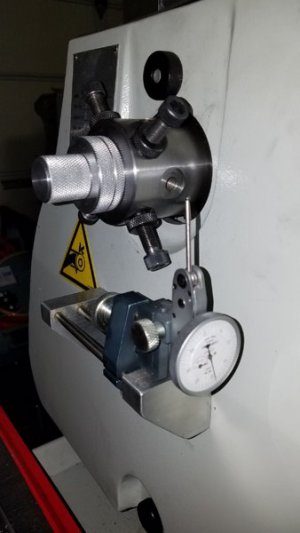
Fully retracted position, the stop body movement is limited by the milled channels in the body, about 3" remains in the spindle.
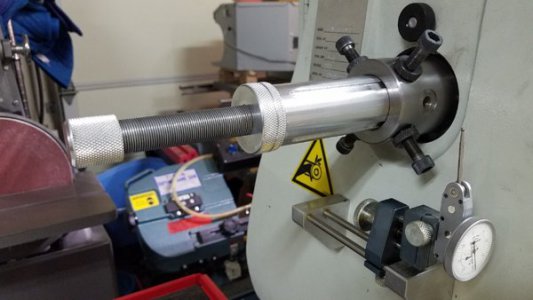
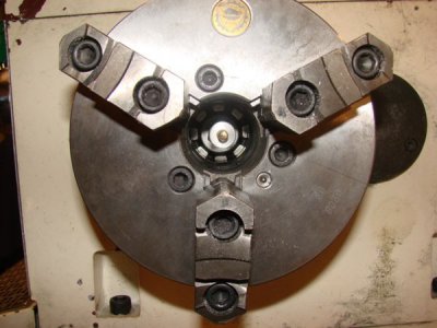
Stop in 3J chuck and the 5C chuck.
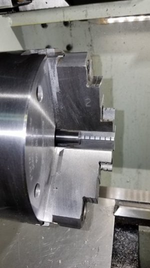
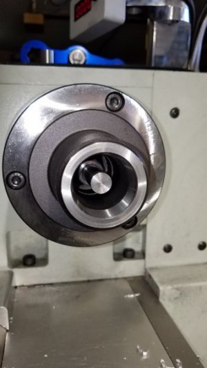
Cutting internal and external threads using a proximity stop system on a PM 1340GT lathe. Each thread cutting pass is 0.01" depth, the thread is a 3/4 - 20:
I wanted to design a stop system that could be used in various capacities with different chucks, that would have both a course and fine stop adjust, and would fit a wide range of diameter stock. Since I use a spindle spider, I figured I could use the spider bolts to lock the body of the stop in place, and then use a fine pitch threaded rod for the vernier adjust. My spindle internal diameter on my PM 1340GT measures 1.59", so I chose some 1.75" x 7" 6061 for the stop body, I turned most of the length down to the spindle diameter except for an end flange (~3/4") and knurled the flange. I then center bored the stop body with an 11/16 drill, and drilled a 3/4" hole to 5". I then internally threaded the 11/16" bored end to 3/4"-20 UNEF. Once threaded, I parted off 1/2" of the flange to create a flange lock ring. I chamfer both the edges before parting it off. The stop body was then put in an indexer and I milled four channels at 90 degree intervals, each one 0.25" wide by 0.075" deep. These channels line up with the spider bolt holes, the brass tips of the spider bolts slide in these channels so the slot's length set the sliding limit and any deformation form tightening the spider bolts is in the channels not on the body.
The stop bar is 3/4" 6061 round stock, in the raw form it is somewhat irregular and the diameter was closer to 0.755". I turned the bar down to 0.749" and then cut a 3/4"-20 male thread about 7" on one end, the other end was tapped with a 1/4" female thread to accept various sized screw in steel tip stops. A cap is needed for the end of the threaded bar to be able to turn the bar for the fine verneir adjustment. The cap is 1" 6061 rod, knurled 1", center drilled the bar stock with a 11/16 drill to 1/2", and then blind threaded the female thread in the cap. Since I use the proximity stop system, I use the internal thread cutter to cut an ending grove within 0.001" of the cap wall, then proceeded to cut the thread. The major diameter is ~0.75, the minor ~0.69, so several passes at 0.01" with a total depth of just over 0.06". I use the cross slide for setting the cutter depth, so the stop position remains the same. Pretty much pushing my internal threading bar insert to its maximum thread depth limit. I did order a 3/4"-20 tap, but at the end of the day I didn't need it. Might have been handy when cutting the 2" 3/4"-20 internal thread on the stop body, this was also at the maximum length of my internal threading bar.
Since the stop bar is supported on the spider end but not the chuck end, you need to add a support ring for the bar that sits at the chuck end. So turned some 6061 ring so it has an OD of 1.59", ID 3/4" and width of 1" chamfered the edges so it slides smoothly into the spindle. I use a set screw to hold it in place, the position is set so that the ring face is even with the end of the headstock spindle with the stop at its maximum stop extension at the chuck end. Steel stop tips were cut from drill rod turned to an OD of 0.749", then two smaller diameter extensions are 0.499"x1.5" and 0.249"x1.5". I turned the diameters slightly under as to not interfere with the clamping of 0.500" or 0.250" stock. Other size tips can also be fabricated. At a later date I plan to make some precession height plates that will fit between the chuck jaws and will be held in place by drawing back on the chuck stop bar which will hold the plate against the face of the chuck body. Royal sells a set of three of these for $300, a bit crazy.
Anyway, the stop bar slides into the chuck body and then is threaded through the remaining 1.5", the flange lock ring is then screwed on and finally the rod end cap. It stays locked in place, but at some point I may consider using a left hand Allan screw in the cap end to lock it on. Screw in the desired tip, slide it into the spider end so the grooved reliefs align with the spider bolt tips. I have a little over 4" of course adjustment in the spider and another 5" from the threaded bar. The tips also can be adjusted, so the 3/4" one is 0.500", the smaller ones are 1.75" from the rod end. Different length stop bars can also be used. The repeatability on my 5C collet holder is under 0.001", so that is good enough for me.
Stop rod with thread inserts, stop body, rod locking ring, stop rod end cap and spindle guide bushing for rod.


Assembled, ready to slide into the spindle.

Inserted and aligned with spider bolts. Fully extended into the spindle.


Fully retracted position, the stop body movement is limited by the milled channels in the body, about 3" remains in the spindle.

Stop in 3J chuck and the 5C chuck.


Cutting internal and external threads using a proximity stop system on a PM 1340GT lathe. Each thread cutting pass is 0.01" depth, the thread is a 3/4 - 20:
Last edited:


