Thread milling gives a weird profile?

strantor

Active User
Registered
Joined
Oct 29, 2012
Messages
1,329
This link should start the video at 43:00 so you can see the operation I am referring to. If that doesn't work, just skip to 43:00.


55 seconds later he makes a comment:

"you could even do thread milling that way but it's not ideal. I think you don't get the proper profile. I think you get some kind of weird re-cutting effect. But don't quote me on that."

Is he right? I can't see why that would be the case. I saw this technique used here and the guy never mentions it:


I need to make a very steep pitch multi-start worm like in that 2nd video and I am considering this method because it would be simplest for me and the pitch is so extreme I think I will run into clearance issues using a single point threading tool.
 
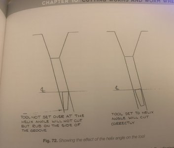
You can single point the high helix angle by simply accounting for it in your single point tool grind.
see the picture below from “gears & gear cutting”

FullSizeRender.jpeg
 
You can single point the high helix angle by simply accounting for it in your single point tool grind.
see the picture below from “gears & gear cutting”

View attachment 457518
Yeah you're right about that. I should have explained the other reasons, which pretty much all boil down to my lathe being not really the right machine for the job. I can't even hit the required pitch with the lathe; I'm going to have to 3D print a temporary gear for upstream of my QCGB in order to make this part. Even if it could hit that pitch with its own gearing I don't think the gear train could take the strain. And it isn't near rigid enough; making a thread this large would be chatter city and probably stall even with back gear. And that carriage is going to be absolutely flying toward the chuck and I don't trust myself to stop it before it crashes much less over travels the exit groove. I would feel a lot more comfortable with Live tooling doing all the work, taking the pressure off both me and the machine while I just turn the chuck by hand.
 
Yep that’s another big issue for sure. I’ve considered trying to make a hob like this on my CNC lathe, but turned out I didn’t need to. So I haven’t attempted it yet. A spiraling attachment for one of my mills would be really interesting but they are rare and expensive and needs a bunch of change gears. So maybe someday a rotary encoder on x and a servo dividing head…. Really would need a repeat job to justify the effort though. anyhow I’m interested to see how you progress. Best of luck!
 
I’m interested to see how you progress
Well I already have the toolpost die grinder attachment so I think am going to go forward with this. Will keep you posted.

Just to make it interesting I'm going to make a prediction. I think it will work just fine. I think I know why he said that but I disagree with it. Here is what I think he is getting at:

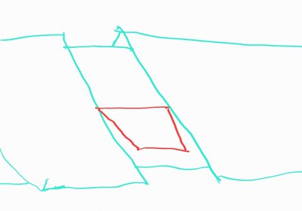
A single point tool making a groove (could be an ACME thread tool or parting tool, whatever):

Screenshot_20230821-091254_Samsung Notes.jpg

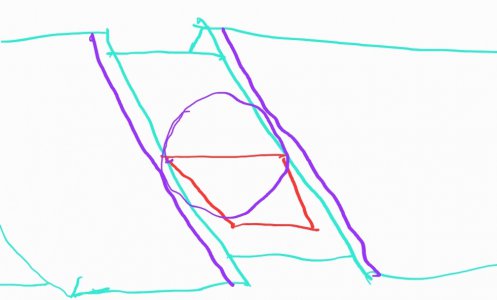
Now if we substitute that tool for a round one that has the same diameter as the single point tool's width, it will cut a slightly wider groove:

Screenshot_20230821-091633_Samsung Notes.jpg

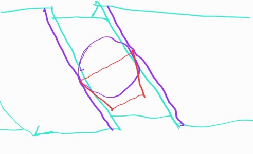
But so would the single point tool, if we re-oriented it like you showed in your book:

Screenshot_20230821-091921_Samsung Notes.jpg

And if this were a circular groove (think: o-ring groove) instead of a helical one, they would cut exactly the same groove.

I if am on the right track about his assumptions then I think that the round tool would be cutting the correct helical groove while the horizontal single point tool would be cutting one that is too narrow because of the aspect at which it is introduced to the work.
 
Just put a hand crank on the lathe!

You can also flip things for really steep pitches and crank the leadscrew.

Don't be afraid of 3dp change gears. I've cut parts on them. They are a great trick!

Sent from my SM-G715A using Tapatalk
 
Just put a hand crank on the lathe!

You can also flip things for really steep pitches and crank the leadscrew.
Yeah I suppose at anything less than 1TPI it makes more sense to crank the leadscrew than it does the chuck! I'll be around 2TPI but it still might be more convenient cranking the leadscrew.


Don't be afraid of 3dp change gears. I've cut parts on them. They are a great trick!
The first few times I read this I thought you meant 3DP (diametral pitch) but eventually I caught on to "3D printed." Yes this won't be my first time doing it either, I have made 3D printed gears out of nylon before, for making metric threads. It worked surprisingly well and my oldest one is over a decade old and still works. But they were all used for cutting reasonable pitches. This one will be under more strain than any 3d printed gear I've ever fooled with (if I cut with traditional tooling, single point). I may be making it a bigger deal than it is, but it just seems a bit much to demand of this 9" toy of a lathe.
 
Shallow cuts, low speed
If you made a round form tool and you had a high speed spindle for your toolpost (doesn't everyone ) you could mill it and have to real cutting load.

I did that with some wacky O-ring grooves on the od of a part, using a dremel and a 1/8" burr. And manually following/cleaning out a 3DP part's groove. Worked!

Sent from my SM-G715A using Tapatalk
 
If you made a round form tool and you had a high speed spindle for your toolpost (doesn't everyone ) you could mill it and have to real cutting load.

I don't know if everyone has a high spindle on their toolpost, but I do, and that's exactly what I'm talking about using.


20230328_180014-jpg.442721


It ain't much but it has increased what I can do with this little lathe tremendously and it was cheap and easy, highly recommended. The roto-zip cost me $25 at a pawn shop and I had it mounted on the lathe in under an hour.

So far I've only used it for abrasive removal and with carbide burrs; this will be its first "milling" job. It will probably not be too impressive but it might work. We will see.
 
Back
Top