The never-ending saga of the Hurco that's "ready to make parts"

Re: Code issue, please help. This stopped being fun a few days ago.

Would the two "blue squares with orange paint" near the white label on the bottom left, be the pots? They look like a pot to me.
Pierre

Yes. The orange paint is glue intended to hold them as they were set at the factory. Those ones are probably not intended for field adjustment. There are also six pots on the top edge of the board.
 
Re: Code issue, please help. This stopped being fun a few days ago.

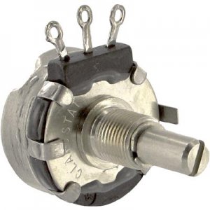
Not at all what I had pictured when pots were mentioned. I was thinking something like this :lmao:
Potentiometer.jpg


The two small ones are near impossible to reach once they are installed on in the assembly. The six on the end would be easier but which one? :dunno:


$(KGrHqR,!qwF!96VtpG)BQYNQT0Wqg~~60_57.JPG
 
Re: Code issue, please help. This stopped being fun a few days ago.

Your Fluke meter is good.

Set your meter on DC volts and put one probe each in the brown? and orange? wires (J2, Terminals 8 & 9?) coming off the amp to be tested.


Start the servos and jog the axis to be tested at 1/10th rapid, the voltage should read about 0.65v and -0.65v, adjust the BAL pot ( that would be the little blue guys at the top of the board) until they do read the same, but with opposite sign, in both directions. When the motor has reached the commanded position, the voltage should be very near 0.

Write a program that moves the table 2 inches, when it stops, the voltage should be near 0, and the DRO should read 2.0000, if not then tweak the BAL and move again. This should bring your machine back to useful again.

If this doesn't resolve the problem, then maybe you will have to do a full tuneup on the drive. Not a huge deal, but a little more work.

I'm semi-retired so I get to ''work'' on the stuff I want to work on. And I'm avoiding going out into the shop to work on a project that I really don't want to do. So helping you with this problem gives me an excuse to do something useful while avoiding the less desirable job. We are helping each other out.
 
Last edited:
Re: Code issue, please help. This stopped being fun a few days ago.

I might actually be able to do this. The contents of the component cabinet are imposing but I'm reasonably intelligent, I should be able to handle this. Turns out the 6 pots are labeled and I found more wiring diagrams that I believe are more specific to what I need to check. That should get me the terminal numbers (or wire colors) I need to put the meter on. I'm tied up tonight but I'll get out there in the morning and take some pictures and post them up the the diagrams and we can get me pointed in the right direction.

Thanks again!
 
Re: Code issue, please help. This stopped being fun a few days ago.

I missed those multi turn pots at the top! Since I was on my 30 minute lunch, I claim that I was too hungry to notice!
Pierre
 
Re: Code issue, please help. This stopped being fun a few days ago.

This should be more helpful.

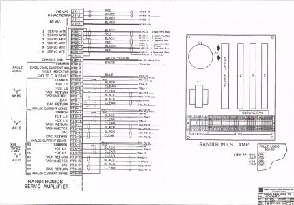
Here is what I believe to be the correct wiring diagram.

board wiring2.jpg

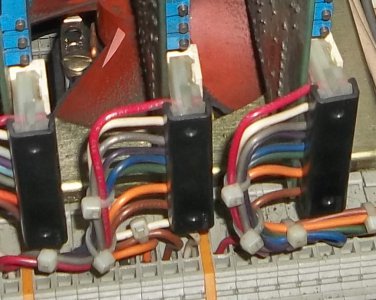
and the corresponding wires in the cabinet (hopefully, although the color coding appears to be off)

board wiring.jpg


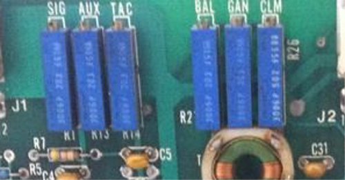
And here are the pots with their labels.

pots.jpg

Which terminals should I be monitoring for voltage; 15 and 16 seem to be the obvious choice but :dunno:?
Which pot is the correct one to adjust? I certainly don't want to go in there turning the wrong knobs.


As an aside. I was looking over the initial piece of material I was working with when we were chasing the coding issue at the beginning of the thread. Although the circles were oversize and had the pac-man mouth, none of them had the offset in the 6 and 12 o'clock position. Not even a hint of it. The final piece I cut was perfect, correct size and no weirdness in the circle. If the voltage is out of adjustment what caused it over the span of a single day? I understand that when things happen, they happen but is there something I could have done to cause this? I havn't been playing around in the cabinet as I was intimidated by the contents. Better to be left alone as long as it works. It did work fine until suddenly one day.

This whole process has been one of a new problem cropping up just as soon as I fix a previous problem. All I want to do is make parts.

board wiring.jpg board wiring2.jpg pots.jpg
 
Re: Code issue, please help. This stopped being fun a few days ago.

The pictures are very helpful.

The DAC (Digital to Analog Converter) and DAC Return, terminals RTB1 19, 20, Orange, and Brown wires are the ones you want to probe.

The pot you want to adjust is BAL

Start the servos and jog the axis to be tested at 1/10th rapid, the voltage should read about 0.65v and -0.65v, adjust the BAL pot until they read the same, but with opposite sign, in both directions. When the motor has reached the commanded position, the voltage should be very near 0.

Write a program that moves the table 2 inches, when it stops, the voltage should be near 0, and the DRO should read 2.0000, if not then tweak the BAL and move again. This should bring your machine back to useful again.

I think you actually had two problems, one with the code, and one with the machine. The pacman shape may have masked the y-axis problem.

You will be making chips in no time.
 
Re: Code issue, please help. This stopped being fun a few days ago.

Okey Dokey

Turned her up as fast as she would go and got full rapid at 93.7. I believe it's higher but that's the top speed in manual mode so I adjusted it to 1/10 of that at 9.3. When I first started I was getting a voltage of .185 in one direction and .175 in another, a full .010 difference. I adjusted the pot about 1/8 turn and got it mostly balanced out. Check out the results in the video which will show more than I can explain.

https://www.youtube.com/watch?v=hgt03ykPvP8&feature=youtu.be


After a few seconds the voltage balances out to .183 in both directions. The wandering appears to be gone but the slight backwards rotation is still present, see 0:42 and 0:49 in the video. It appears to be reduced from maybe 5º to about 1-2º so it is an improvement.

Most of the stuff I need to cut in in the 30ipm or less range so I figured I'd try it at 30 and see what I got. The voltage appears to balance out in a similar manner to the video above just at a higher voltage and that makes sense. At this higher feed the wandering is back although it does seem to be lessened.

Also, if you look in the range of 0:33 on the video you can see a slight forward jump in rotation as the axis is stopping. Not sure if this is a new development or just something that was overlooked with the other problems.


Time was not on my side this morning so I didn't get a chance to run the program that was suggested to move the axis and check the measurement but I'm not convinced that would affect the wondering or back-turn although I am admittedly not even a novice at this stuff.

Where should I go from here?
 
Re: Code issue, please help. This stopped being fun a few days ago.

I think you are on the right track. You may have to tweak the BAL pot a bit to get rid of the little backward movement. I only watched the video a couple of times so I didn't see everything. I'll study it a bit more later, and read the manual again. I would like to see what happens when the table is moving under program control, when you get time that would be helpful.

I'll update this post later, stay tuned.
 
Re: Code issue, please help. This stopped being fun a few days ago.

I was thinking I need to run it a 30 since that's basically where I live and make sure the voltage is balanced there. I might experiment with that later today and see what I get.

I believe the max rapid for the machine is the the 270 range so 30 would be closer to 10% than the 9.3 I was using. I'll dig through the manual I have with me and see if I can find what the machine rapid actually is.
 
Back
Top