Synchronome clock build

zuckerman457

Registered
Registered
Joined
Nov 26, 2013
Messages
11
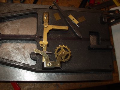
Howdy, I'm building a variant of a Shortt-Synchronome clock, here's Sync parts that I've done so far, sync parts 24nov13.jpg
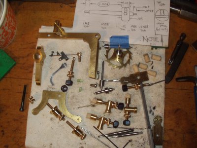
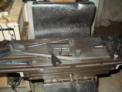
with the clockback on my Gorton 8d milling machineclock back.jpg Its the first clock I've ever built. I've been using the Engineering in Miniature build series by Isaacs, along with the Hope-Jones DIY article, and feeding in some of the info from "Accurate Clock Pendulums" by Matthys, and using zuckerman "feels right" input too.
I hope to have a steel pendulum rod swinging under power sometime in February, if not the Invar36 one. The 16.5 lb bob is annealed 360 brass with the Matthys temp compensator scheme that I am modifying, instead of an Invar tube I want to use a quartz tube inside the bob, with an annealed 360 brass compensator exposed beneath the bob. I'm using my variation of the Shortt suspension trunnion for my clock, 3/4 dia. Invar bar on either side of the spring, Invar nuts on a Invar trunnion with sync style 1/8 pin . I've got both phosphor bronze and berillium copper shim stock for springs, along with a lot of phosphor bronze bar stock that I can cut down into one piece spring stock, for when I have my surface grinder running well...
I have an old mahogany box from a Pratt&Whitney super micrometer that I'm going to use for the case, its from WW2 and is old growth mahogany.
I have an old Sync slave clock, and when I have this clock working well in the house, am planning on buying a Microset with most of the bells and whistles so I can see how well ( or poorly) I built it, then I'll start drawing/machining the Shortt. For the Shortt, I've got a piece of Pyrex tube 1/2 wall x 6 ID x 60 for the tank, am scrounging for bell jars now...
Plan is to pour 6 tons of concrete sometime in '14 in the backyard..... 'cause my 100+ year old house just ain't stiff enough....I'll build a shed over the plinth, super insulate it, and see how the Sync runs when mounted on a stiff plinth and in a temperature controlled room, use the Microset for data acq, while the Shortt is being built.
Right now I'm gathering all the bits for building a heat treat oven. I have not been able to find a heat treat company who can anneal my Invar rods in what I consider the correct manner, or, they would charge me for heating an oven that will hold an F16 in it! so I'll build my own oven and do it myself.
My electric oven will be 4.5x4.5x60 internal, vertical with a bottom drop door, nitrogen inert atmosphere...am also planning on cryogenic treating the Invar rods when the heat treatment is done, figure it can't hurt, may help..and from an engineering viewpoint I won't know either.. HA!
zuckerman story, ( true!) One of the salesmen I talked to at a HT company asked if I could cut my rods in two so he could lay them on his oven floor.


sync parts 24nov13.jpg clock back.jpg
 
Do you have the EIM article dates? Any chance of reprints anywhere? /thanks.
I have a frame cast by high school students maybe 20 years ago, plus blueprint plans, but there are problems. If they were based on the EIM series, taht might help....

Howdy

EIM has back issues, in Nov2012 I paid 30.80 GBP +9 GBP shipping for the 14 issues needed. todays exchange is roughly 65$ US. I do not know the current back issue pricing, probably the same cost as then.

feb 87vol 8#9, through dec 87vol 9#7,then Mar 88vol 9#10 through may 88vol 9#12. I received a combination of original magazines, and stapled xerox copies..

You should also get the Hope-Jones book "electric clocks and how to make them" it also has the instructions on how to build, but in an older form , expecting you to know machining. (to be an engineer, to use the old world British word for home shop machinists.)

The EIM article has a couple of problems, it's missing a couple of simple parts to build, and at least one critical spring is not listed, and a couple of incorrect dimensions.. the Hope-Jones book will help.

BUT, that critical spring is not in Hope-Jones book either.. It is the catch return spring, from my understanding, that spring was made by the factory in several different forms, hair spring, single leaf spring.. I haven't gotten to the point of my build where it is needed... yet.. I'll figure something out...

What problems does your casting have? I have two castings from College Engineering Supply in the UK, one of mine had the gravity arm pillar cast in the wrong place (I figure the casting pattern had it mounted on a single offset screw and it got turned 180 degrees before it was cast) I machined it off and attached one in the correct place, and the other frame was cracked and rewelded, that one needs to be annealed before I attempt machining it.
17dec build log.jpgtoday 17dec, picture of the build log, lots of work yet to do.. all finicky precision placement and/or adjustment of bearings ..

good luck with your build, if you have any questions post them here so other builders can reference them.

17dec build log.jpg
 
Hi
Regarding the synchronome article, if you look at my web site, see botom of page, and send me a E mail, I may be able to help.

Brian.
 
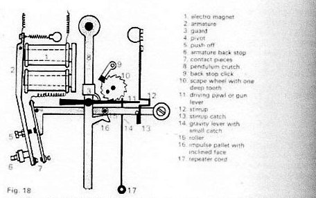
In this diagram the latch looks as if it is biased by its suspension spring.
Brian.

img368.jpg

img368.jpg
 
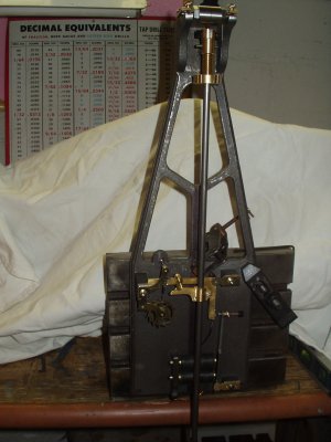
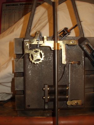
Howdy, I still have a lot of work to do, but here are pics of the first mockup of the clock.mockup4 19dec13.jpgmockup619dec13.jpg WOOT! to get to this point has been a long involved path....

still have LOTS of details left, make the detent roller, install the stops, wiring posts, polish and lacquer all the brass bits, wrinkle paint the clockback, finish work on the clock case... AND make the heat treat oven for the Invar rod..

mockup4 19dec13.jpg mockup619dec13.jpg
 
Is this a clock that might have been used as a time standard back in the day? The pictures in the last post above reminds me of a clock which we had at work, which until the early 1960's was used a a time standard to regulate the +- in frequency to keep synchronous clocks accurate. The clock is still in our control centre in Ontario and hasn't run since 1990, but ran until then, when our control centre moved the fellow who looked after it retired. I spent a lot of time in front of it dreaming of the day when I would make a replica.
Michael


Howdy,
Yes, the Synchronome master clock would be one of several different makes that were built in the day, between 1905-1950 or so.. take a picture and post it, I'm sure somebody here can identify it if it is not a Synchronome. The Sync's I could identify, not so much any other, unless the makers name is on it.. The Sync Master clocks do not have their name attached to it, except on the slave clock face, which would have the Sync name painted or inscribed on it...
I mentioned the article for building a Synchronome that is in the Engineering in Miniature magazine. You do NOT need a cast iron clock back, which at this time is unavailable from the British company that was casting it. The article gave a blueprint for a fabricated clock back also. It really is a simple clock to build, a lathe, drill press, files and a jewelers saw is really all you would need...
Over the years, on the British ebay site, I've bought Synchronome copy parts that were made by British home shop machinists', back in their day...some with really high quality, and some, well, charitably, not as good....but even those bits worked ok... I would recommend it as a first clock, there is not a lot of high precision work. When the Synchronome company was selling kits for the hobbyists to build, their advertising prominently mentioned 5 seconds accuracy a week.... pretty good even now...
thanks, drive carefully
 
Howdy,

I've spent most of the day touching the clock, adjusting, learning how and what makes it run.
First pic is the running clock sitting on the workbench.

2nd pic is the bob with the compensator I'm using, bob is bored to within 1/2 inch of the top, a quartz tube supports the bob, and a 360 brass tube is the compensator, this is using Robert Matthys scheme with an Invar rod.

3rd picture is the test bench I built to check thermal expansion of an Invar rod. the heat pad and thermometer is easy to see, the .0001 indicator at the end is not so easy to see. when I get fired up, I'll recheck the unannealed rods I have and post the numbers..

I just checked the clock and after 3 hours! it was still going well... no clue if it will continue, but I have hopes that the adjustments I have made were what the clock needed to run reliably...

The telling point I see is that the gathering jewel travel had extended its reach across the count wheel teeth, which tells me that the pendulum is running with power to continue. I have a cheap battery clock for comparison, and the sync is running just a little fast right now.. this is a 1018 steel rod for the pendulum, 52 inches long, and there is roughly a 2 inch total swing left to right at the bottom end.

I'll be wandering down to the shop every now and then for the rest of the night, checking to see how it is running...

If tomorrow morning you hear a loud WOOOHOOOO , its me ...


john robinson
mechanician
world land speed record holder Bonneville Salt Flats
H/GCC dodge colt 144.396 MPH
1967 BSA Victor 107.371 MPH at Bonneville
USAShooting Air Pistol National Record holder
Antarctic Ice Core Driller 3,331.538 meters
Grandpa
 
Last edited by a moderator:
Howdy,
Well, the clock has been running for more than 24 hours now, still on the workbench and not really ready for prime time.
At first, the clock was running about 7 minutes/hour fast before I made a temperature compensator change, now its around 9 seconds/hour fast, although I'm not really setting the clocks' rate, only playing with the clock, as I figure I deserve a little play time after all the work of building it.
I've made two major adjustments, I replaced the detent roller with a smaller diameter one, that fixed a problem with it occasionally hanging up above the tip of a tooth and stopping the clock, and I replaced the brass temperature compensator tube with a shorter one, as that was easier to do than cutting the quartz tube that is inside the pendulum bob. That change brought the clock time closer to "reality".
I notice that the pendulum swing length has changed (longer) with the slowing of it, I had not known (or thought of) this would happen. With this longer slower pendulum, I see that the gathering jewel is now reaching left across the tooth closer towards the detent roller, and it seems like the pendulum is adjusted more to the left than the right, so I may have to either adjust the length of the gathering arm, or move pendulum suspension to the right to compensate. I put Dykem marker on the pallet face to see the track of the gravity arm roller, it is straight down the center of the face.
The gravity arm catch is working very well, I did not install a spring to 'help' it catch the arm spring, and may not need to after all.The clock itself is not very loud when resetting, but the Synchronome slave clock is very klunky and noisy, even with my old man poor hearing...I may investigate bumper installation in the slaves.
Anyway, I'm pleased with the progress so far...
thanks and drive carefully
john robinson
 
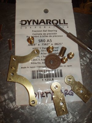
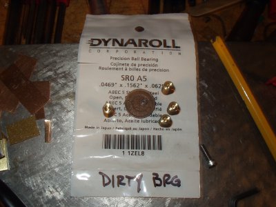
Howdy, have finished remachining of the Synchronome clock pivot bearings, replacing the clock type broached pivot bearings with Dynaroll ball bearings, PN# SR0 A5, open style, .0469 bore diameter.
That's one of the bearings on the 1906 Indian head penny. The brass bearing holders are 1/4 x28 threaded rod, they are screwed into the clock back with lock nuts, to adjust for endshake. The bearing plates are machined for ball bearings also.
bearing plates 26jan14.jpg

sync bearing holders 24jan14.jpg bearing plates 26jan14.jpg
 
Back
Top