Starret 196f inside indicator attachment.

BruceW

Registered
Registered
Joined
Jul 16, 2020
Messages
27
This has probable done to death but here goes.
Well I have looked for a inside indicator for a while and the only one with any reach seems to be the starret made for the old back knob indicator.
What happened ?
30-40 yrs ago their were plenty around at least where I did my time.
Any way I had a look on the interweb and only found one hit that anyone had made.
There seemed to some math involved and precise mill drilling to make it work.

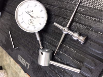
Here’s my take on it.
found a bit of aluminium 1" round bar about that long.
Measured the dail indicators barrell?
Drilled the hole out . Mine was easy 0.312"
stuck it on the indicator and figured I’d have a little wiggly room up and down for adjustments.
Drill and tapped it for a grub screw. May make a knurled thumb screw one of these days.
Machined down some s/s rod I had that has never rusted.
And yes it squealed in protest all the way machining to a few tenths under the 0.250" indicator attachment hole.
proceeded to drill a 1/4 inch hole in the dail Indicator holder piece using the tool post to hold it square.
Then used a bit of Loctite to fix it in situ.
Ohhh hell everyone confused?
here is a few pics.
9CED87C1-D362-4D33-BC3C-729591AF3BD7.jpeg
8A753AE2-FAF4-4F53-867B-7C38156900C3.jpeg
Easy enough to align on the centre of the ball of The indicator where you want it.
Simple really.
I suppose there could be some errors of measurement but good enough for indicating internal bores true.
Now just have to figure how to put my tenths indicator on it with that little arm they have.

Hope it helps someone.
Bruce.
 
This has probable done to death but here goes.
Well I have looked for a inside indicator for a while and the only one with any reach seems to be the starret made for the old back knob indicator.
What happened ?
30-40 yrs ago their were plenty around at least where I did my time.
Any way I had a look on the interweb and only found one hit that anyone had made.
There seemed to some math involved and precise mill drilling to make it work.

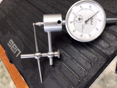
Here’s my take on it.
found a bit of aluminium 1" round bar about that long.
Measured the dail indicators barrell?
Drilled the hole out . Mine was easy 0.312"
stuck it on the indicator and figured I’d have a little wiggly room up and down for adjustments.
Drill and tapped it for a grub screw. May make a knurled thumb screw one of these days.
Machined down some s/s rod I had that has never rusted.
And yes it squealed in protest all the way machining to a few tenths under the 0.250" indicator attachment hole.
proceeded to drill a 1/4 inch hole in the dail Indicator holder piece using the tool post to hold it square.
Then used a bit of Loctite to fix it in situ.
Ohhh hell everyone confused?
here is a few pics.
View attachment 346699
View attachment 346700
Easy enough to align on the centre of the ball of The indicator where you want it.
Simple really.
I suppose there could be some errors of measurement but good enough for indicating internal bores true.
Now just have to figure how to put my tenths indicator on it with that little arm they have.

Hope it helps someone.
Bruce.
Nice work, Bruce.
 
I like it, may have to make one myself. This deserves a Stupidly Simple Design Award.
 
Very nice. How did you make the pivoting arm?

And did you turn and drill/tap the bracket in which the pivoting arm resides?
 
re Indicator Attachments; for this variety, accuracy is not governed first by the indicator.

The starting point is the pivot, and the contact balls being equidistant from pivot center axis.
2] that indicator bracket is centered on the respective ball polar axis.
3] minimizes contact travel so the indicator remains closest possible position to that pole. Any deviation from polar axis introduces sine error, where linear contact becomes a side load. That can be lessened using the flattened 'mushroom' contact on the indicator, loosing minimal travel.
4] as internal indicating typically focuses on determining location, repeatability is the goal. Not physical dimensional measurement, instead accuracy is secondary.

While still useful, those attachments predate widespread availability of test indicators. It works inside, but they were employed far more often outside; on Toolmaker buttons. Before widespread locating of X-Y coordinates like a milling machine can, establishing center distances of bores were set in layouts, and represented physically by Toolmaker buttons. Their small diameter allowed compact center distances, but more importantly very small deflections of indicator readings. This could be done on a drill press, tapping the plate in to register, clamped to face plate of a large lathe, or of course 4 jaw chuck. That's also an advantage in round column drill presses with turn tables, making centering easier - sometimes.

Not long ago, we did this very thing. Our milling travel capabilities did reach the distances required on a 6' long plate. Before hand, those coordinates were buttoned and one near a reference feature. Unclamping the plate, and swiveling the head were needed to reach those coordinates. Inspection proved locations attained were just under half the .005 full tolerance allowed, [+/- .0025] meaning near perfection. The rough locating was by .001, then finalized by .0001 test indicators.
At least two contributing factors at work here; discounting the DRO and manual mill. Shop is not temperature controlled, but layout, the work, and inspection were stabilized. Other and probably more critical is the material was assured flat, and the mill was re-trammed for the three moves, limiting/correcting Abbe errors.
 
That attachment was designed to work with a back plunger indicator. Nice adaptation to a standard indicator
 
That attachment was designed to work with a back plunger indicator. Nice adaptation to a standard indicator
Absolutely. That one originated with 196 back plunger, but they were prevalent with short travel AGD 'drop' or 'plunger' bodies as well, in straight and 90° needles. They're still sold today.
 
Back
Top