- Joined
- Feb 8, 2014
- Messages
- 11,176
I thought I would write this up while the parts are in the vibratory deburr tub.
One of the projects in alloy’s Shizouka build is to build a spindle tach. see the full machine build here: http://www.hobby-machinist.com/threads/shizouka-an-s-build.33868/
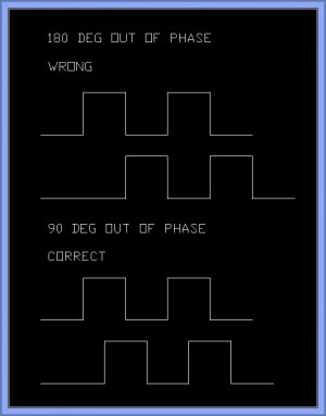
I decided to show this build in a separate thread to show my thought process and work holding. The tach input is from two 4mm proximity sensors that look at the gear teeth. When one is pointing at the gear tooth, the other is looking at the root. This gives an A/B signal to give both speed and direction to the computer. To the computer it will look just like an encoder.
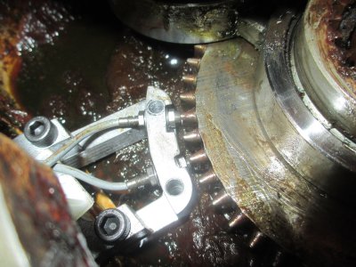
The prox sensors have a sensing range of 0.6mm (0.023 inch) so they have to ride very close to the gear, they’ll be set at about 0.015 clearance. One of the challenges was to figure out where the spindle C/L is in relation to the port on the side of the housing. I spent about an hour measuring points in the housing so I could get the relationship figured out. It was all done with combination squares and calipers. I used the squares as depth gages, then measured the distance with calipers.
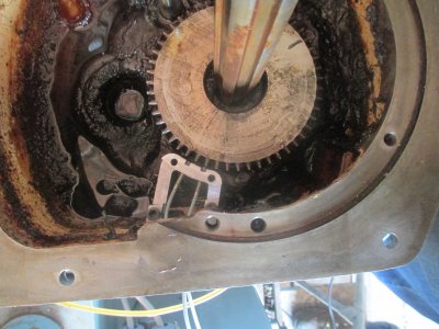
The approximate location of the prox sensors
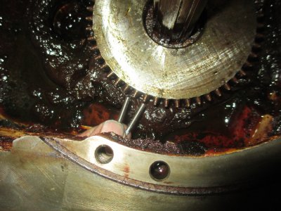
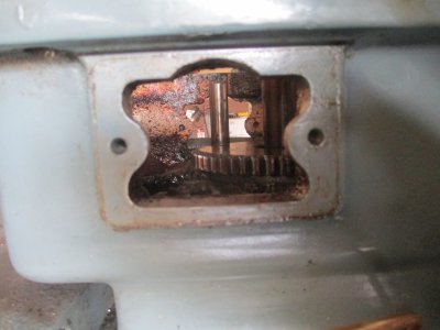
Looking in from the outside. I checked the location of the vertical shaft in the background and determined that it was on the port centerline. That gave me a baseline to work from in the Y-axis, then it was reasonably simple to determine the distance to the spindle in that axis. With a couple of combination squares, I was able to get the x-axis dimension.
Then off to the computer with the data. Here is the concept drawing
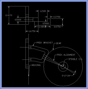
I was originally going to make the bracket in one piece and carve it out of a chunk of 4x4x3 aluminum bar stock. A couple of problems with this, I wasn’t that confident in my spindle location, and I didn’t have the material. Building it in one piece with no possibility for adjustment would have been bad practice, and the geometry was pretty complex and would have been a bear to machine. I decided to make it in three pieces; the Cover Plate, the Spacer and the Prox Bracket. and then bolt it together. That way I can have a little adjustment and is simple to build. All of the material used was miscellaneous drops I had kicking around
First I roughed out the Prox Bracket and the fixture that holds it to the rotary table. Why do you need to do this on a RT when doing the work with a CNC mill? You’ll see later. This entire project was machined in my head before I ever made a chip. It had to be done in a logical order to make the fixturing work. The part was machined to thickness, the holes drilled (and tapped), and countersunk as needed. The countersunk holes are for attaching the work/fixture to the RT.
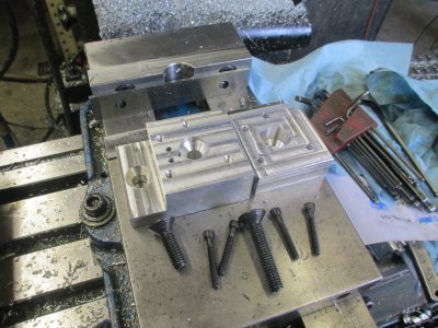
Dialing in the RT, the table center has to be known for the next operations. (-5.000, -2.000 in this case)
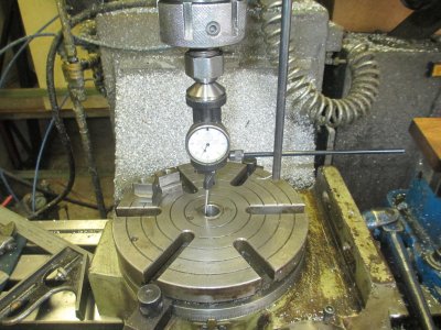
Ready to go on the RT
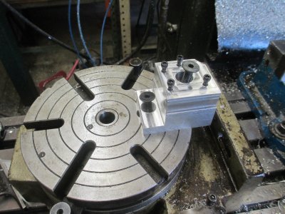
So the next step it to locate the fixture on the RT, this is done setting the indicator on a known location and noting the value, then using that same value on the indicator to locate the fixture. I cranked the table over to where the face of the fixture needed to be, then with the bolts a little snug, I tapped the fixture into position, in both the X and Y axis until the indicator read exactly the same as the reading I set at the datum point. This took about 5 minutes. Then tighten the bolts and double check the readings. The fixture will not be removed from the RT until I am satisfied that the parts are correct and fit properly, that way, if I need to make modifications, the fixture is in a known location.
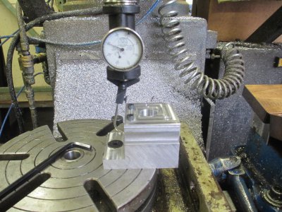
Almost ready to make chips. You’ll note that two of the 10-24 cap screws are not installed. The work is held with the two 10-24 cap screws and one of the 3/8 flathead screws so it’s anchored tight.
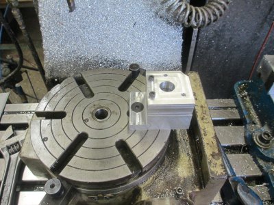
Now the step down surface has been machined, so the other two 10-24 cap screws have been installed. Also the 3/8 flat head screw has been removed so I can drill though the countersink. You will remember that the fixture was also countersunk, now it’s time to use that, because in the next operation, the area of the hole will be removed.
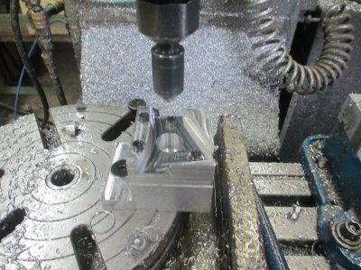
Profiling the part:
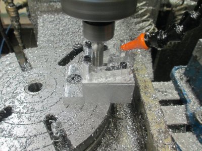
And finishing the inner profile with a ¼ end mill, also putting the flats on the inner surface for the nut bosses. That is not an arc; those are two angled flats that are perpendicular to the prox sensor bore.
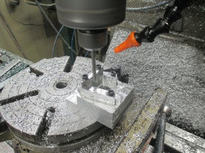
And the semi-finished part.
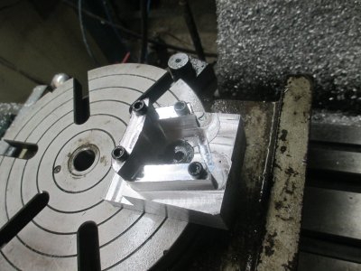
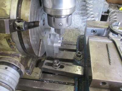
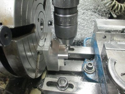
Now for the next operation. Drilling the holes for the prox sensors. This is why it was mounted on the RT. The prox sensors have to point at the spindle C/L to line up with the gear teeth, and to get the correct spacing, the distance from the spindle C/L and the RT has to be correct. So in this case, that is 5* 17’ 39’’ off of the C/L, the easiest way to do this was to use the RT.
Now you also see what the step in the fixture is for, it clears the drill chuck. I drew up the chuck and the RT to get the height of the fixture and to make sure everything would clear. The counter bores are to provide clearance for the front nut on the prox sensor and to move metal away from the sensing face.
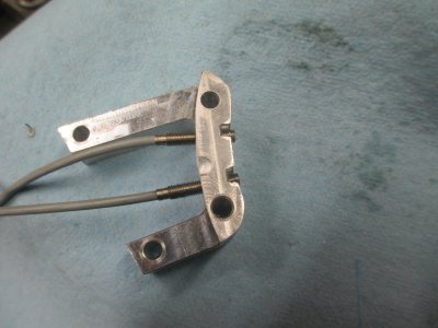
And the finished bracket prior to deburr.
Now on to the next piece, the Spacer:
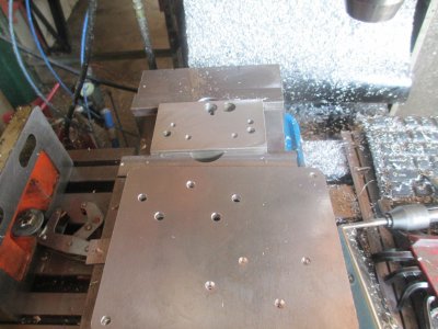
This part is much simpler, and screw right on to the fixture for machining. I grabbed a chunk of Swiss cheese aluminum off of the shelf, and found a corner that I could get the Spacer out of. I drilled the hole pattern using the same G-code that was used to drill the holes for the Bracket.
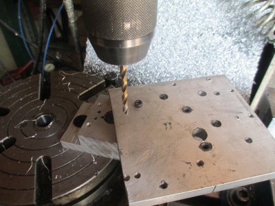
Ready to start cutting.
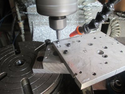
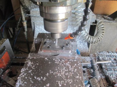
First pass. About 5 minutes to cut the whole part
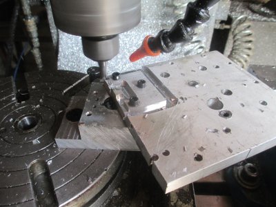
And drill the screw holes to 0.265 , this will give a little wiggle room for adjustment. Then drill and tap the Cover Plate mounting holes (not shown)
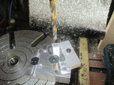
Tapping the screw holes ¼-20 in the Bracket. The cap screws were just finger tight for this operation, I wanted the tap to find it’s own center in the hole.
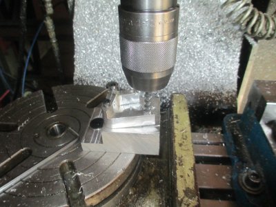
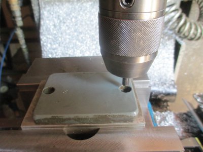
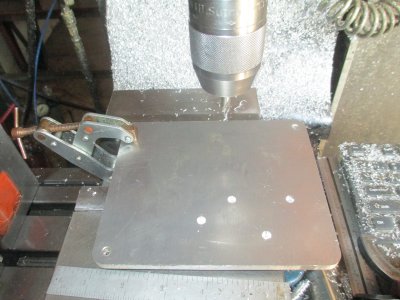
The final piece, the Cover Plate. I grabbed another Swiss cheese chunk of aluminum off the shelf and used it as a backer for the machining operation. I located my ‘’0’’ point by using a dowel pin in the chuck and the original cover plate as a pattern. I had already drawn up the cover plate, but it needed to be located on the backer.
Well I exceeded my photo limit for this post .....to be continued in the next post
.
.
One of the projects in alloy’s Shizouka build is to build a spindle tach. see the full machine build here: http://www.hobby-machinist.com/threads/shizouka-an-s-build.33868/
I decided to show this build in a separate thread to show my thought process and work holding. The tach input is from two 4mm proximity sensors that look at the gear teeth. When one is pointing at the gear tooth, the other is looking at the root. This gives an A/B signal to give both speed and direction to the computer. To the computer it will look just like an encoder.

The prox sensors have a sensing range of 0.6mm (0.023 inch) so they have to ride very close to the gear, they’ll be set at about 0.015 clearance. One of the challenges was to figure out where the spindle C/L is in relation to the port on the side of the housing. I spent about an hour measuring points in the housing so I could get the relationship figured out. It was all done with combination squares and calipers. I used the squares as depth gages, then measured the distance with calipers.
The approximate location of the prox sensors

Looking in from the outside. I checked the location of the vertical shaft in the background and determined that it was on the port centerline. That gave me a baseline to work from in the Y-axis, then it was reasonably simple to determine the distance to the spindle in that axis. With a couple of combination squares, I was able to get the x-axis dimension.

Then off to the computer with the data. Here is the concept drawing

I was originally going to make the bracket in one piece and carve it out of a chunk of 4x4x3 aluminum bar stock. A couple of problems with this, I wasn’t that confident in my spindle location, and I didn’t have the material. Building it in one piece with no possibility for adjustment would have been bad practice, and the geometry was pretty complex and would have been a bear to machine. I decided to make it in three pieces; the Cover Plate, the Spacer and the Prox Bracket. and then bolt it together. That way I can have a little adjustment and is simple to build. All of the material used was miscellaneous drops I had kicking around
First I roughed out the Prox Bracket and the fixture that holds it to the rotary table. Why do you need to do this on a RT when doing the work with a CNC mill? You’ll see later. This entire project was machined in my head before I ever made a chip. It had to be done in a logical order to make the fixturing work. The part was machined to thickness, the holes drilled (and tapped), and countersunk as needed. The countersunk holes are for attaching the work/fixture to the RT.

Dialing in the RT, the table center has to be known for the next operations. (-5.000, -2.000 in this case)

Ready to go on the RT

So the next step it to locate the fixture on the RT, this is done setting the indicator on a known location and noting the value, then using that same value on the indicator to locate the fixture. I cranked the table over to where the face of the fixture needed to be, then with the bolts a little snug, I tapped the fixture into position, in both the X and Y axis until the indicator read exactly the same as the reading I set at the datum point. This took about 5 minutes. Then tighten the bolts and double check the readings. The fixture will not be removed from the RT until I am satisfied that the parts are correct and fit properly, that way, if I need to make modifications, the fixture is in a known location.

Almost ready to make chips. You’ll note that two of the 10-24 cap screws are not installed. The work is held with the two 10-24 cap screws and one of the 3/8 flathead screws so it’s anchored tight.

Now the step down surface has been machined, so the other two 10-24 cap screws have been installed. Also the 3/8 flat head screw has been removed so I can drill though the countersink. You will remember that the fixture was also countersunk, now it’s time to use that, because in the next operation, the area of the hole will be removed.

Profiling the part:

And finishing the inner profile with a ¼ end mill, also putting the flats on the inner surface for the nut bosses. That is not an arc; those are two angled flats that are perpendicular to the prox sensor bore.

And the semi-finished part.

Now for the next operation. Drilling the holes for the prox sensors. This is why it was mounted on the RT. The prox sensors have to point at the spindle C/L to line up with the gear teeth, and to get the correct spacing, the distance from the spindle C/L and the RT has to be correct. So in this case, that is 5* 17’ 39’’ off of the C/L, the easiest way to do this was to use the RT.
Now you also see what the step in the fixture is for, it clears the drill chuck. I drew up the chuck and the RT to get the height of the fixture and to make sure everything would clear. The counter bores are to provide clearance for the front nut on the prox sensor and to move metal away from the sensing face.

And the finished bracket prior to deburr.

Now on to the next piece, the Spacer:
This part is much simpler, and screw right on to the fixture for machining. I grabbed a chunk of Swiss cheese aluminum off of the shelf, and found a corner that I could get the Spacer out of. I drilled the hole pattern using the same G-code that was used to drill the holes for the Bracket.

Ready to start cutting.

First pass. About 5 minutes to cut the whole part

And drill the screw holes to 0.265 , this will give a little wiggle room for adjustment. Then drill and tap the Cover Plate mounting holes (not shown)

Tapping the screw holes ¼-20 in the Bracket. The cap screws were just finger tight for this operation, I wanted the tap to find it’s own center in the hole.

The final piece, the Cover Plate. I grabbed another Swiss cheese chunk of aluminum off the shelf and used it as a backer for the machining operation. I located my ‘’0’’ point by using a dowel pin in the chuck and the original cover plate as a pattern. I had already drawn up the cover plate, but it needed to be located on the backer.
Well I exceeded my photo limit for this post .....to be continued in the next post
.
.
Last edited:

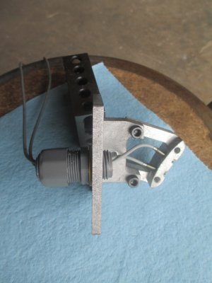
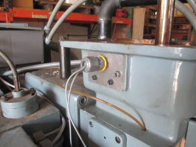
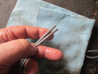
 Needless to say it didn't work on the encoder input.