- Joined
- Sep 22, 2010
- Messages
- 7,223
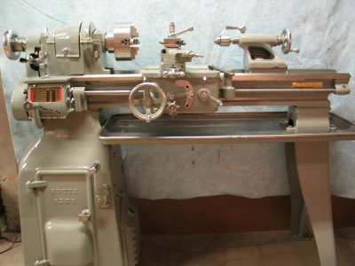
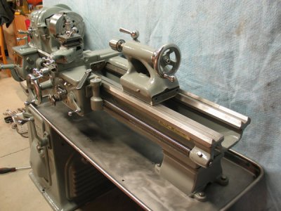
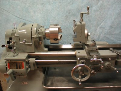
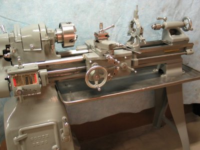
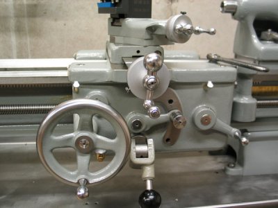
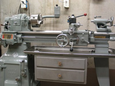
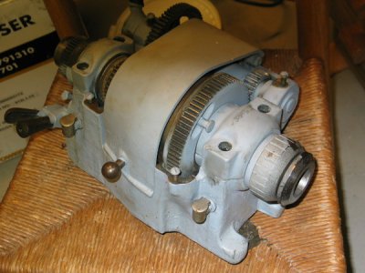
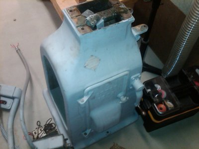
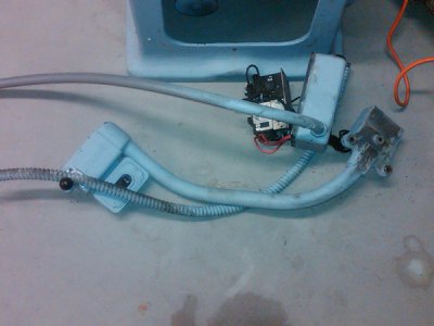
here is the Craig's List photo. And some of the assemblies:
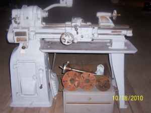
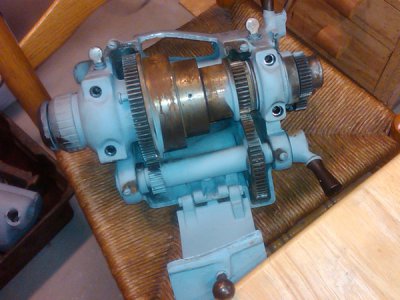
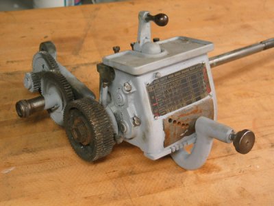
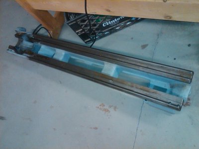
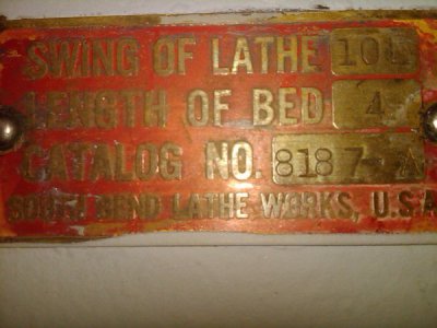
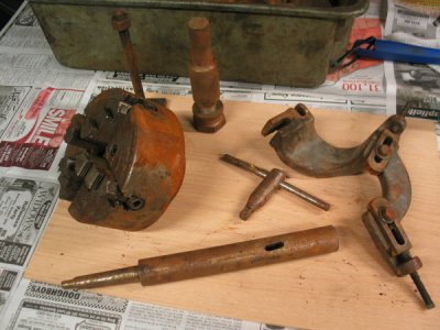
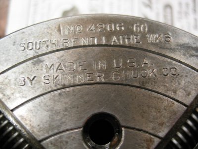
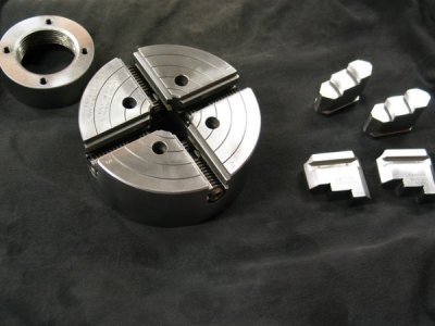
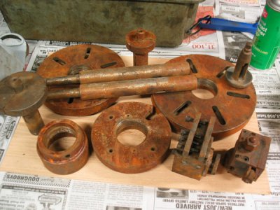
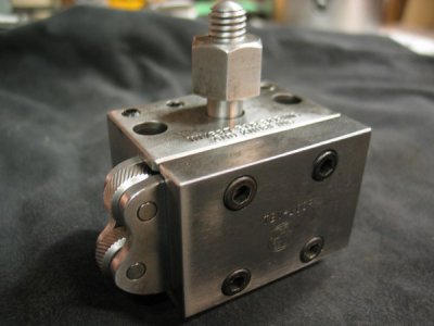
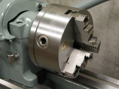
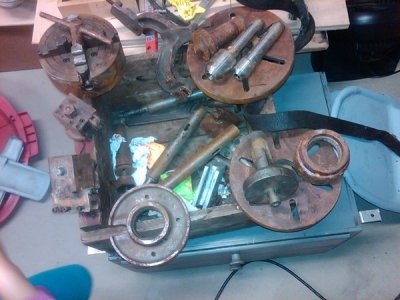
Here's all the rusted tooling (looks like I'll need a 3-jaw chuck):
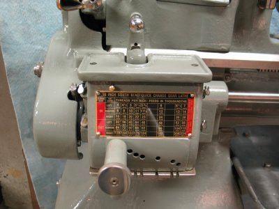
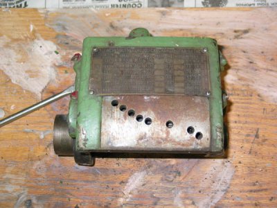
Ok, enough with the boring stuff. Onto the restoration! I disassembled the machine into it's separate assemblies. I've read through most of the restoration threads and learned quite a bit about what this will be like. I thought I'd start at the bottom with the base and work my way up. But due to the sheer weight of the bottom motor cabinet, I opted to begin with the QCGB.
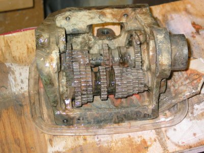
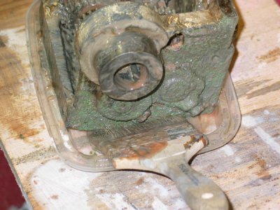
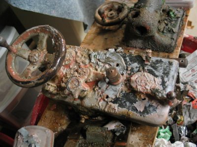
What a mess this thing was. No real rust problems here, just a ton of caked on crud.
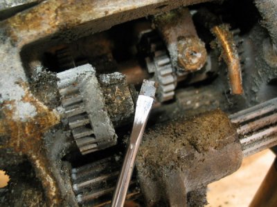
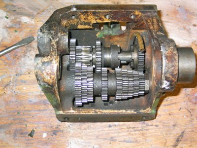
I got most of it taken apart, but hit a snag. I don't know how to remove the two main shafts? Any guidance, or threads would be greatly appreciated.
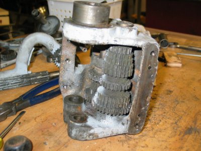
tried to make some progress with the instructions & parts list, but to no avail... In the picture below, the pin isn't coming out. It seems to be mushrooming. Is this common or am I doing something wrong, I mean should I just keep trying to whack this thing until it comes out?
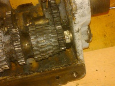
Then, I have two more problems.
1. When the pin DOES finally come out, what methods have people used to hold the gears in place (and not ruin them), while trying to unloosen that bolt?
2. Then, for the second shaft (the complex one) the instructions mention that the last gear #33 is pressed on. I'm guessing I need to use a large drift pin to hammer on the shaft? If so, looking at the below picture, which side do I need to hammer on? Or is hammering the wrong method?
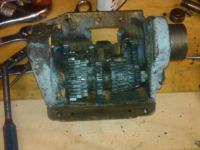
Here's one side
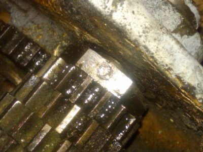
Here's the other
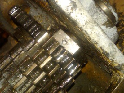
Ok, I thought, the nut is replaceable and even the shaft (because the threads got chewed up as well).
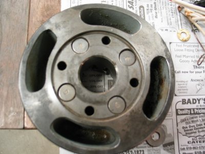
So then it was onto the other shaft - the really difficult one to remove. Well, I had previously downloaded a "how to" (on the Hobby Machinist site) on disassembling the QCGB. The person used a brass rod and hammered it out. I did the same thing. Only, the end of the shaft was getting banged up and then all progress stopped. There is (what looks like) another taper pin in the gear right after the pressed on one? The picture below shows what looks like one, and it appears to not go directly through the center of the shaft?
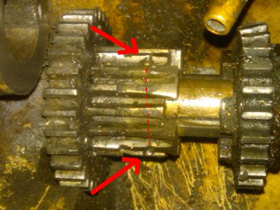
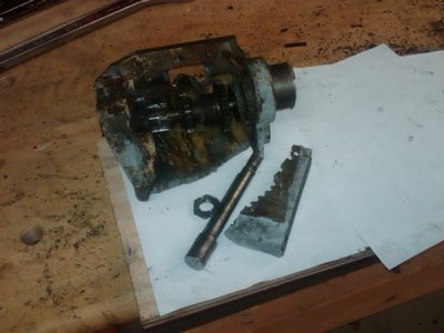
Anyway, as I was banging on it, the whole enclosure slipped out of the rig that was holding it. It flew across the room, hit the concrete floor and busted. Why the hell is this so hard to do?
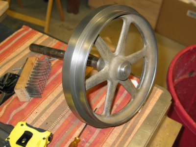
Pulley ready for primer
.
.
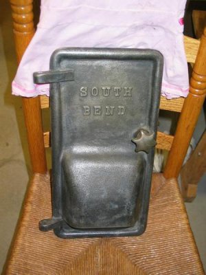
Door ready for primer
.
.
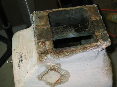
Base with Citristrip doing it's amazing job
.
.
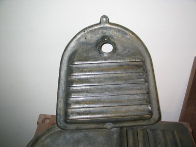
Another door ready to get primed
.
.
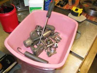
Most of the base parts after being degreased in Purple-Power
.
.
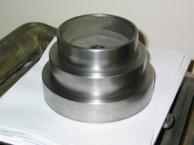
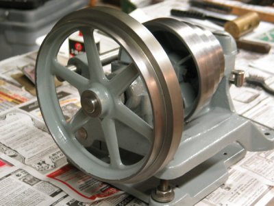
The main pulley cone for the base with a little scotch-brite treatment
.
.
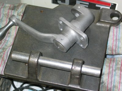
The handle was sand blasted by my neighbor. I'll get him to do the other carriage & spindle parts.
.
.
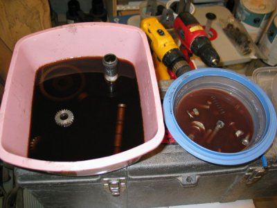
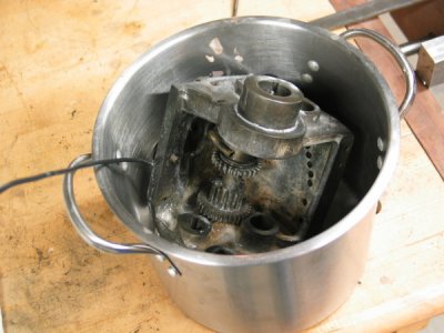
Some gearbox parts cooking in Purple Power
Counter-shaft in various stages
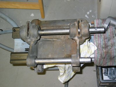
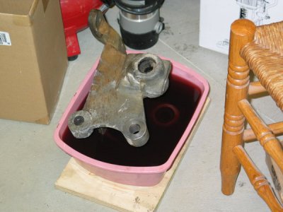
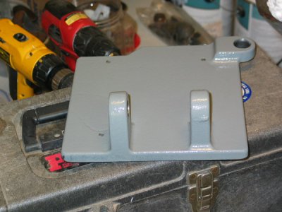
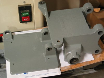
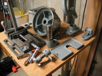
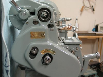
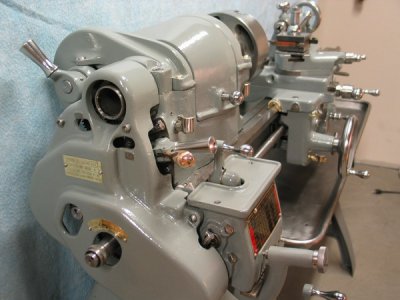
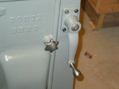
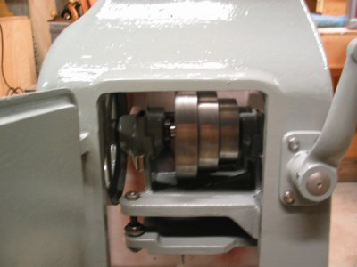
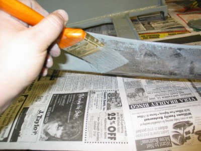
Here's some various pictures of the base, after paint.
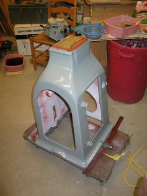
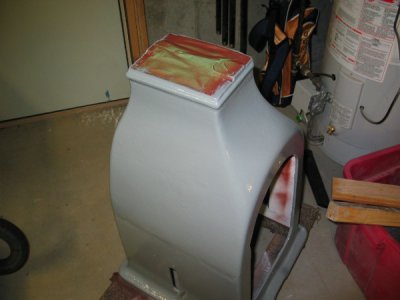
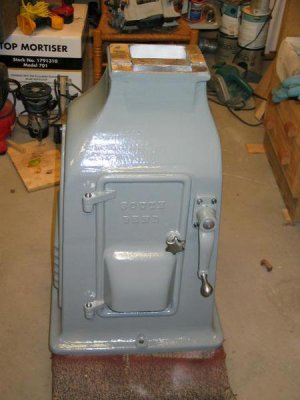
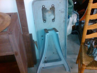
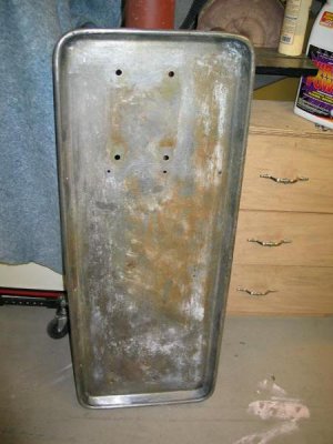
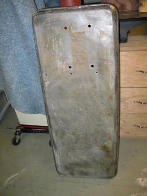
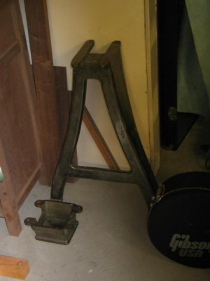
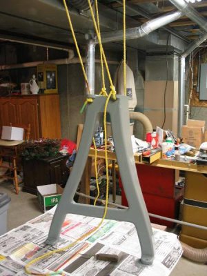
Here is the legs and chip pan.
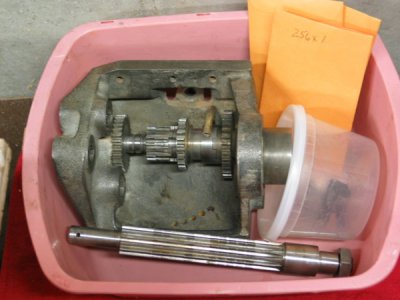
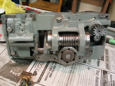
Some gear box photos. Got this from eBay. Luckily, this was in really nice condition with no wear on the bushings and the gears are also nice.
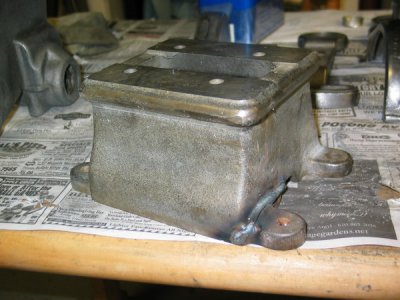
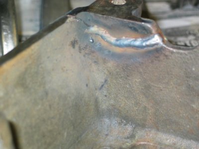
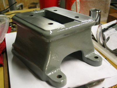
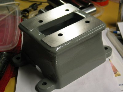
Here's some shots of the base unit that sits on the legs and supports the bed. Now I know what you're thinking - and yes, I went and welded cast iron
I had no idea (at the time) that you can't (or shouldn't). But it did work - just not sure how strong it was. Oh well, lol...
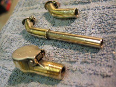
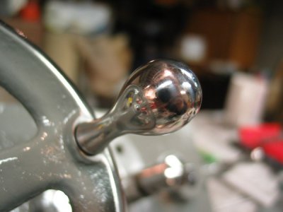
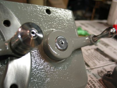
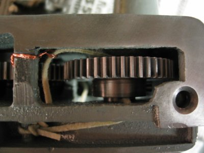
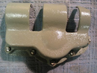
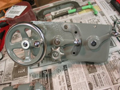
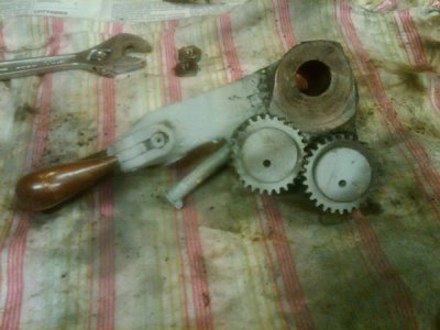
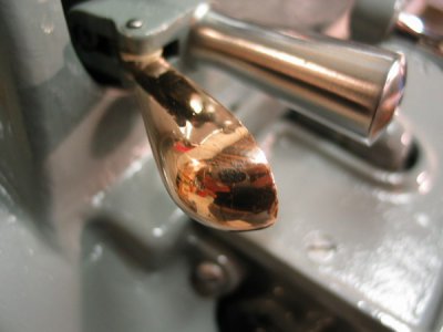
The main shaft on this reverse lever is being repaired. I just placed it here for the photo.
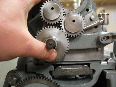
This is the box found on the back of the machine.
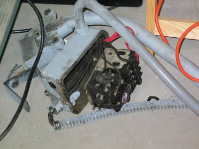
Drum switch
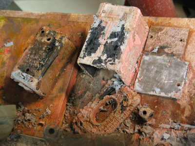
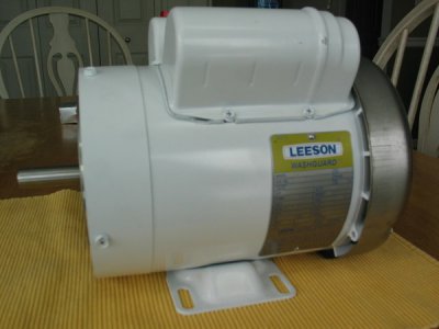
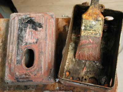
And this box was found right next to the drum switch - (What does this do???)
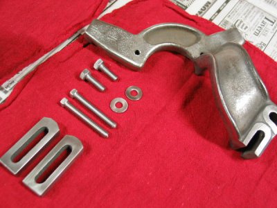
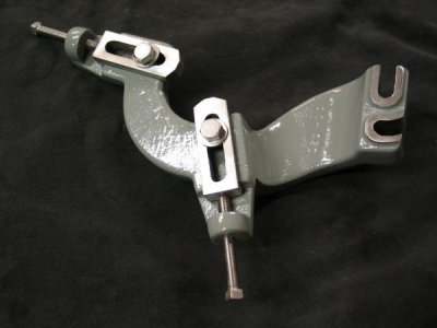
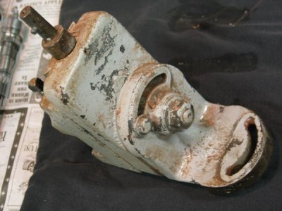
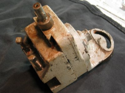
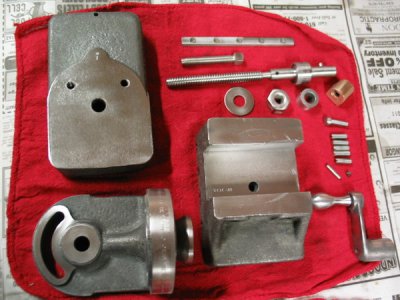
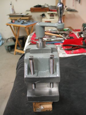
Milling Attachment (before & after)
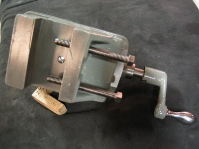
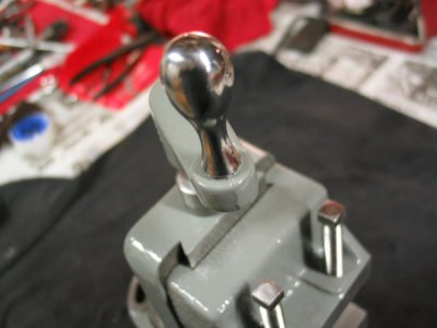
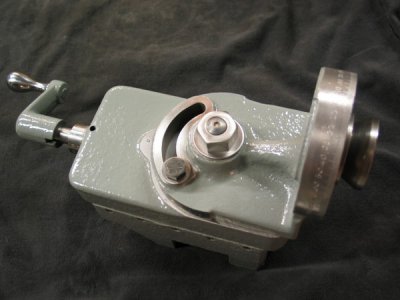
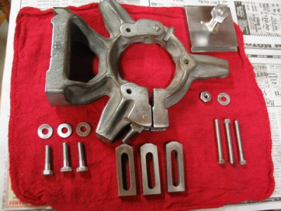
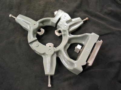
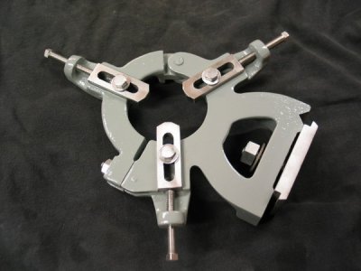
Steady Rest
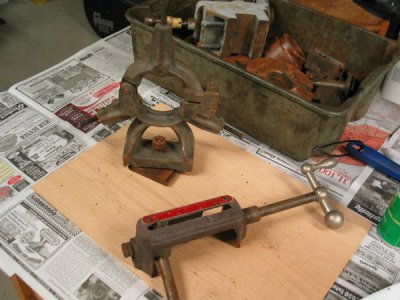


Here's all the rusted tooling (looks like I'll need a 3-jaw chuck):

Ok, enough with the boring stuff. Onto the restoration! I disassembled the machine into it's separate assemblies. I've read through most of the restoration threads and learned quite a bit about what this will be like. I thought I'd start at the bottom with the base and work my way up. But due to the sheer weight of the bottom motor cabinet, I opted to begin with the QCGB.
What a mess this thing was. No real rust problems here, just a ton of caked on crud.

I got most of it taken apart, but hit a snag. I don't know how to remove the two main shafts? Any guidance, or threads would be greatly appreciated.

tried to make some progress with the instructions & parts list, but to no avail... In the picture below, the pin isn't coming out. It seems to be mushrooming. Is this common or am I doing something wrong, I mean should I just keep trying to whack this thing until it comes out?

Then, I have two more problems.
1. When the pin DOES finally come out, what methods have people used to hold the gears in place (and not ruin them), while trying to unloosen that bolt?
2. Then, for the second shaft (the complex one) the instructions mention that the last gear #33 is pressed on. I'm guessing I need to use a large drift pin to hammer on the shaft? If so, looking at the below picture, which side do I need to hammer on? Or is hammering the wrong method?

Here's one side

Here's the other

Ok, I thought, the nut is replaceable and even the shaft (because the threads got chewed up as well).
So then it was onto the other shaft - the really difficult one to remove. Well, I had previously downloaded a "how to" (on the Hobby Machinist site) on disassembling the QCGB. The person used a brass rod and hammered it out. I did the same thing. Only, the end of the shaft was getting banged up and then all progress stopped. There is (what looks like) another taper pin in the gear right after the pressed on one? The picture below shows what looks like one, and it appears to not go directly through the center of the shaft?

Anyway, as I was banging on it, the whole enclosure slipped out of the rig that was holding it. It flew across the room, hit the concrete floor and busted. Why the hell is this so hard to do?

Pulley ready for primer

.
.
Door ready for primer

.
.
Base with Citristrip doing it's amazing job

.
.
Another door ready to get primed

.
.
Most of the base parts after being degreased in Purple-Power

.
.
The main pulley cone for the base with a little scotch-brite treatment

.
.
The handle was sand blasted by my neighbor. I'll get him to do the other carriage & spindle parts.

.
.
Some gearbox parts cooking in Purple Power

Counter-shaft in various stages


Here's some various pictures of the base, after paint.


Here is the legs and chip pan.


Some gear box photos. Got this from eBay. Luckily, this was in really nice condition with no wear on the bushings and the gears are also nice.


Here's some shots of the base unit that sits on the legs and supports the bed. Now I know what you're thinking - and yes, I went and welded cast iron
I had no idea (at the time) that you can't (or shouldn't). But it did work - just not sure how strong it was. Oh well, lol...


The main shaft on this reverse lever is being repaired. I just placed it here for the photo.


This is the box found on the back of the machine.

Drum switch

And this box was found right next to the drum switch - (What does this do???)

Milling Attachment (before & after)


Steady Rest


