- Joined
- Feb 5, 2015
- Messages
- 662
This is a piece that I wrote some years ago but it may be worth recycling. Note that it’s heavy on words and light on pictures in the beginning but the words are important to absorb and understand to get the most out of the topic.
There is a tendency for many hobbyists to over-emphasize the use of carbide lathe tools and end mills. Carbide tooling is usually unnecessary and more expensive for most of our applications. I'm speculating that maybe many use this type of tooling because it's easy to buy an off-the-shelf pre-ground part (as opposed to grinding a HSS tool that will generally produce superior results in a hobbyist environment).
When I was a youngster, shop teachers spent a lot of time talking about cutting tools and their shapes. A normal practice was to introduce the common chisel as a form of knife - something any boy could readily understand with the aid of his "Barlow" pocket knife. Visualizing a number of important concepts is helpful by simplifying them in this manner. Apparently not many shop classes are offered these days so some of the fundamentals aren't well understood.
As has been mentioned by many knowledgeable folks, here and elsewhere, it's not wise to jump into machine tool operation without having basic knowledge of the cutting process. Grinding cutting tools is necessary if you want to obtain the best performance from your lathe, shaper or planer. Since the two latter tools are not that common in a home shop, let’s emphasize the lathe cutting tools.
This used to be considered an indispensable skill which always preceded the operation of the machinery that used the tool. Even in my fifth grade woodshop class, a student never even handled a plane until he had first become familiar with the chisel and how to sharpen it.
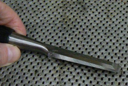
The chisel is the simplest and most universal cutting tool - that is what I was taught. All other cutting tools - whether lathe, mill, shaper, planer or drill - use a chisel cutting edge. It's just that simple and also just that complex. Back in the day, it was necessary to learn how to make things with hammer, chisels and files before touching the on/off switch of a machine tool. The lessons learned were invaluable for many reasons, some of which are:
• Patience
• Layout/measurement techniques
• Cutting characteristics of various ferrous and non-ferrous materials
• Tooth count of files and metal-cutting saws, why the specific configuration and how to use them
• Cutting flat surfaces and keyways with hand-held tools (hammer/chisel)
• Sharpening these tools to obtain best results on different materials
When discussing the chisel configuration, the cutting angles have to be considered first. If the chisel is inclined too far (so that the angle of the chisel is approaching horizontal) then the cutting edge will likely skid off the surface without removing material, "scuffing" the edge of the tool. If the chisel is angled too far in the other direction (the angle of the chisel approaching vertical) then material will not be cut cleanly, the pressure will simply deform the material rather than removing a chip - think of the operation of a center punch.
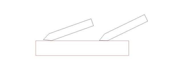
When the angle is correct, a chip is removed from the workpiece; by controlling the angle (and cutting pressure) of the chisel, we can produce chips of varying thickness. (Think of this as the "DOC" of a machine tool.) The chisel cannot cut unless there is back relief of the cutting edge - without relief, the chisel will skid across the material without cutting.
In the first sketch below, there is back relief of the tool but the cutting angle is so large that the chisel is more of a blunt instrument than a true cutting tool. The amount of pressure required to produce a chip from this tool will be excessive, the tool will try to dig in, producing inconsistent chip thickness and the workpiece will mostly deflect away from the tool - most of the power used to attempt the cut in the workpiece is wasted.
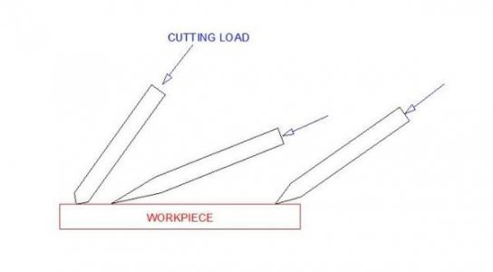
In the second configuration, the angles may be appropriate for a wood chisel but definitely not for a chisel intended to cut metal. The cutting edge will quickly break down and fracture under pressure. Additionally, because of the thin cross section, the heat generated by the cutting process cannot be conducted away from the tip of the tool so the tip will quickly anneal.
If the tip becomes soft, it will acquire a rounded edge which cannot produce a chip. This configuration will require frequent sharpening if it is to be useful and can only be used on very soft materials (like wood). In the third sketch, a compromise angle is shown, sharp enough to produce a chip but with enough cross-sectional area to conduct heat (from the work expended in the cutting process) away and to cut for some time without the edge breaking down and requiring frequent re-sharpening.
All cutting tools require sharpening unless they are throw-aways, like insert tooling. The tool material of choice - in 90% of our applications - would be high speed steel. Not to say that carbide tooling isn't - or can't be - useful but this material is designed to be used most effectively with rigid machinery having respectable horsepower and high spindle speed, unlike many of the imported machines that hobbyists usually purchase or old American iron, made before carbide became common.
I mentioned that one of the above chisel configurations would be appropriate for woodworking applications and that brings up another important point. Sharper tools (less angle, more relief) can generally be successful when working softer materials. NOT always, however, especially when materials such as brass are being cut - there is a tendancy to "grab" the cutter with potentially disastrous results.
(One of my middle fingers has severed tendons as a result of a "spin-out" with a brass workpiece some forty years ago. Needless to say, this impairs my freedom of speech, LOL.) Materials like brass should be worked with zero cutting relief or even a few degrees of negative rake. We'll get to that shortly …
Although it is possible for a cutting tool to have geometric characteristics that can be useful on many different materials, the geometry will always be a compromise and might not be appropriate for the production of more than a few parts at a time.
I've so far used a chisel to make a few points about the angles of a cutting tool but this simple tool doesn't experience the stresses induced on a machine tool cutter. There is very little heat buildup within the chisel working edge because the duty cycle is so low. (Duty cycle, in this case, being the amount of work done over some period of time.)
The craft of grinding HSS tools is mostly limited to lathe and shaper tooling although it doesn't have to be. I'll confine this short discussion to the lathe because I'm most accustomed to grinding lathe tools. There are thousands of pages of literature explaining the process of optimizing a lathe tool for a particular application – reading this stuff exceeds my patience threshold and is mostly unnecessary for my needs. I use three or four basic configurations and my tooling inventory is limited to some small plastic drawers in one of those forty-drawer cabinets available at the hardware store.
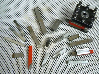
Noting that my lathes are small (8 x 18 and 11 x 36), the following types of tooling - in my opinion - are appropriate for hobby lathes up to 14 inches. My shop-built lathe toolholders are usually configured for 3/8 square HSS blanks or standard 3/8 brazed-carbide tools.
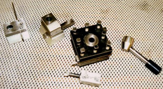
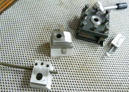
Parting tool holders are configured for 3/32 x 1/2 HSS parting tool blanks, like the one in the next photo - it's in the holder clamped into the 4-way toolpost. At the bottom of the same photo is a stand-alone parting tool holder machined for 3/32 x 1/2 blank.
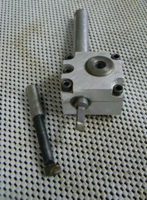
I have a few 1/2 square blanks for forming tools which I rarely used. Boring holders accommodate 1/2 diameter shank brazed carbide (C2, C6) boring bars but most of my boring needs are better served with 1/4 square HSS blanks, ground to suit individual jobs. A slotted adaptor like the one shown in the boring bar below for 1/4 HSS blanks is a five-minute chore and generally cuts freely, producing a better finish with less spring-back than the typical imported brazed-carbide boring bars:
A large advantage of using 1/4 HSS blanks is how quickly they can be ground (not to mention that they are not costly) compared with a 3/8 blank, for example. These small tools are capable of surprising depths of cut (.250 in mild steel), if I can cool the cutting edge. They are always handy for cutting wood and plastics because it takes only a few seconds to grind a sharp rake, lots of relief and then hone to a razor edge. For cutting these materials, the usual test is to sharpen until the tool can easily cut paper.
Grinding a lathe cutting tool is similar in concept to grinding the cutting edge of a chisel which is the entire point of this post. Chisels are ground with more relief than absolutely required because they are free-hand guided and therefore need angular adjustment of around +/- 15 degrees for flexibility of purpose. The lathe tool is tightly secured in the toolpost and its orientation to the workpiece is usually (although not always) constant. That makes the grinding task and the optimal configuration for various materials easier to derive.
I haven't operated a machine tool in a production environment in many years and haven't learned much about tool grinding since I was taught back in the sixties. I don't measure angles, rake, front and side relief because I have no capability to precisely guide the toolbit. I just hold the thing against the grinding wheel after setting the angles by eye and dip it in water every five seconds or so. Clearly my methods are unscientific and would be completely unproductive in an environment that required me to make 300 parts a day for a week, sharpening the tool only twice a day.
A beginning machinist may not easily detect subtleties in angles when examining a cutting tool. But it doesn't take long to develop an eye for angles that work best in certain materials. This is how I "eye-ball" my lathe tools for various materials:
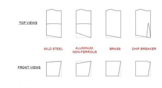
Here is a photo of tools ground to these approximate geometries. They are laid on a hand towel and are not necessarily resting horizontally (in addition to the fact that the photo is not very high quality). The two carbide tools at the left of the photo have almost no top rake but front and side relief have been ground - these are intended for cutting steel at a relatively high spindle RPM.
The three HSS 3/8 tools in the center are ground for aluminum and are fairly sharp; several of them have generous nose radii to produce a nice finish. On the far right is a 1/2 square tool ground to cut brass on either side. There is no top rake but the tool is ground for front and side relief (on both sides).
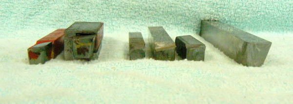
I want to emphasize that I don't measure any of these angles and that the sketch and photo may include "sharper" angles than many sources would recommend. But for my small machines, the aspect ratios usually work and make the small lathe motor work a little less harder.
If these angles don't produce acceptable results, the geometry is easily corrected. Using magnification to observe problems (chipped cutting tool edge, workpiece material tearing, "rolled" edges, "scuffing" below the cutting edge, any indication that the tool is improperly adjusted for height, too sharp or not sharp enough) will provide hints as to how the tool needs to be modified or adjusted.
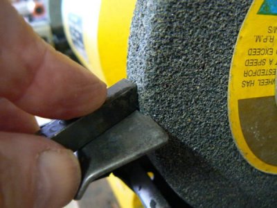
Let's run through a typical tool grinding chore, grinding a 3/8 square HSS tool for conventional cutting (toward the headstock). First, set the tool rest on your grinder for the approximate angle you wish to produce. It's helpful at first to use a known good-cutting tool bit to help you set the tool rest angle. With the tool bit firmly supported by the tool rest, grind the front relief, pausing frequently to cool the tool in a nearby container of water:
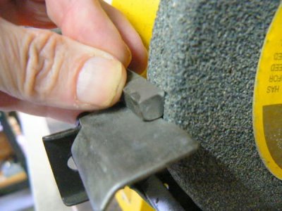
Repeat the process by grinding the side relief of the tool - don't allow the HSS to discolor from heat, keep it cool:
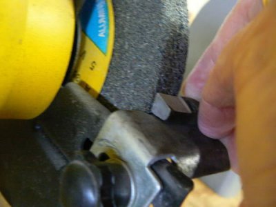
Now flip the tool 180 degrees and grind the top rake:
You can take a light pass on the three ground surfaces with a finer grit wheel, being very careful not to change the angles of the relief and rake. Then make a quick polishing pass on a disc sander. I've found that the easiest way to do this is to remove the tool rest, hold the tool bit in contact with the disc while supported on the lip of the lower guard of the sander. Now with the ground angle firmly held against the disc, "blip" the on/off switch of the sander - just a quick "on" then "off". The disc will rotate only a turn or two and that's adequate to take the wire edge off the tool bit. Do this on all three ground surfaces:
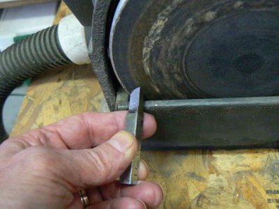
Note that the grinding wheel shown in the above photos isn't an optimum choice for tool grinding but I''m a thrifty guy - the wheel came with the inexpensive grinder and I'll likely use it until a half inch or so of the wheel diameter has eroded, LOL.
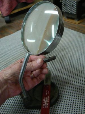
Now examine the tool under magnification and lightly polish the tip of the tool to produce a small radius if one is desired. Do this carefully so that you do not damage the sharp edges you've just spent several minutes establishing ! Test the tool bit by passing it lightly across your thumbnail in the cutting direction - it should remove a light sliver of the nail surface. (Note that inexpensive diamond hones in several grits are really helpful for touching up cutting tools - even the lips of end mills.)
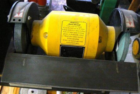
Not too long ago, finally acknowledging that my hands were getting mighty shaky, I made this little setup for my grinder. It’s simply a long steel “table” that extends across both grinding wheels. There are mounting tabs welded to the table underneath, to mate with the existing grinder tool rest mounts (the HAZ can bee seen on top of the table).
A sliding tool rest can move across the table to any point. A pivoting guide is adjustable in fifteen degree increments (although I keep telling myself that I should modify it to five degree increments). The lathe tool to be sharpened is held or clamped against the guide and passed repeatedly over the face of the grinding wheel.
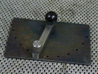
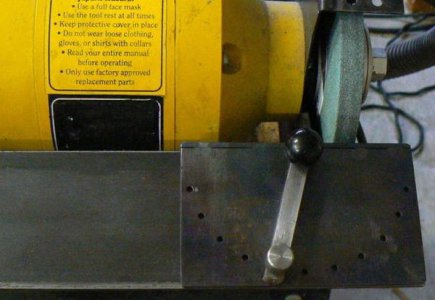
This insures a consistent angle, much better than repetitive hand grinding, cooling the tool in water, hand grinding again and so on. This usually results in multiple facets rather than the single angled cutting face that is desirable.
When turning long, slender pieces (with or without follower rest or center), sharper geometries are required to prevent the workpiece from deflecting away from the cutting tool. Facing operations usually require a broader cutting angle and a greater tip radius - the heat buildup will be greater than axial turning (because the SFPM will almost always be greater than recommended as the tool nears the periphery of the workpiece).
Visualizing the chisel cutting edge can be helpful in other ways. A good example is sharpening twist drills by hand. Think about how metal can be removed, in a circular fashion, with a tool that resembles a chisel except for the shape. Imagine how the drill must be simultaneously rotated and angled to obtain a "rotating chisel" shape. Practice the motion with larger drills until muscle memory allows manipulating smaller drills with the same motion but MUCH more quickly.
Even easier to imagine is the plunging operation of a center-cutting end mill. The shape of the bottom of the end mill is precisely that of a chisel, with cutting angles refined for workpiece material - a compromise, of course. Once the CUTTING process has been firmly established in one's mind, the SHARPENING process will soon follow.
Perhaps the very easiest visualization, when comparing the chisel geometry to metal cutting machinery, is the shaper/planer type of surfacing machine. In point of fact, sharpening tools for a shaper doesn't differ that much from sharpening for a lathe except that the angles may vary - shaper tools can be both steeper and shallower.
The shaper may have a small motor but it has an energy storage device in the form of a flywheel and since the duty cycle is intermittent, it doesn't require as much horsepower as the continuous cutting process in a lathe. Therefore the tools can be a little less sharp, which prolongs tool life between sharpening. On the other hand, also because of the duty cycle and the cooling between strokes, it is possible to use a sharper edge for special work without the edge overheating as quickly as it would in a lathe.
Sharpening a parting or grooving tool is ridiculously simple if a commercially available blank is used. For hobbyists, probably the best choice is a 3/32 wide by ½ tall blade and a suitable holder. To sharpen, all that’s required is to set the tool rest angle on your grinder and grind the same radius on the parting tool as the grinding wheel.
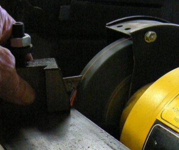
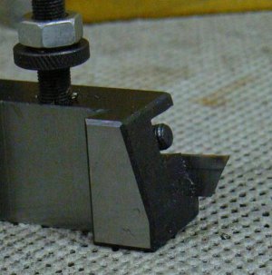
Please note that I performed the above operation so that I could photograph the process. I didn’t bother to adjust the grinding table to a better angle so the parting tool has a MUCH more acute angle than the desirable configuration. A tool with this much front rake will quickly break down with use. I’ll re-sharpen at the correct angle before using it, be assured !
A Note On Machine Setups Related To The Chisel Concept
Most of the operations performed on my 8 x 30 vertical mill don't stress the machine very much - the workpieces are generally non-ferrous and held in vise, collet block or in a 4-jaw chuck mounted to a rotary table.
Occasionally a table setup is required that requires using step-blocks, clamps, tee-nuts, studs and so forth … augmented by blocks of wood, metal scrap and anything handy to position and support the workpiece. This type of impromptu setup can lead to scrapped parts, damaged tooling and operator injury, especially for novice machinists. I have contrived a mental "test" for any unusual mill setup to evaluate stability. This is sort of simplistic but please bear with me for a moment.
Knowing the path of the cutting tool that must produce the desired machined surface is critical. (Do you recall all of the advice written about welding - how experts always suggest a "dry run" of the process before striking an arc?) Keeping the tool path in mind, recollect that the milling cutter is a rotating chisel, and imagine the path of the cutter across the workpiece and how the setup will react.
Take a mental step back from your setup. Visualize placing a chisel anywhere along the tool path and striking the chisel with a hammer to remove a chip. Your brain, processing the visual information, along with past experience and some intuition, can suggest (or hint) at the stability of the setup. Before activating the machine and feeding the tool, consider the forces involved … imagine a metal-cutting chisel rotating with the considerable torque produced by a motor of 1 to 3 HP.
If you're still in doubt about your setup, tap the various clamps and supports with a small brass hammer in the direction that the cutting tool will apply a load. After performing this test on all of the clamps and supports, tap the clamping studs and make sure that each produces the "ping" sound of a properly torqued stud, not a dead "thud" sound that indicates something in the setup has loosened under load or vibration. (It's also good practice when using unconventional setups to periodically stop the machine and test rigidity and tightness of the clamping devices.)
I have been lucky over the past forty years that not one of my fairly small machines has ever experienced a crash. I can't take much credit for that because my work is small and can usually be securely clamped. BUT visualizing the "chisel" action of the cutting tool in any unusual setup - lathe or mill - may have prevented an embarrassing snafu … or several of them.
There is a tendency for many hobbyists to over-emphasize the use of carbide lathe tools and end mills. Carbide tooling is usually unnecessary and more expensive for most of our applications. I'm speculating that maybe many use this type of tooling because it's easy to buy an off-the-shelf pre-ground part (as opposed to grinding a HSS tool that will generally produce superior results in a hobbyist environment).
When I was a youngster, shop teachers spent a lot of time talking about cutting tools and their shapes. A normal practice was to introduce the common chisel as a form of knife - something any boy could readily understand with the aid of his "Barlow" pocket knife. Visualizing a number of important concepts is helpful by simplifying them in this manner. Apparently not many shop classes are offered these days so some of the fundamentals aren't well understood.
As has been mentioned by many knowledgeable folks, here and elsewhere, it's not wise to jump into machine tool operation without having basic knowledge of the cutting process. Grinding cutting tools is necessary if you want to obtain the best performance from your lathe, shaper or planer. Since the two latter tools are not that common in a home shop, let’s emphasize the lathe cutting tools.
This used to be considered an indispensable skill which always preceded the operation of the machinery that used the tool. Even in my fifth grade woodshop class, a student never even handled a plane until he had first become familiar with the chisel and how to sharpen it.

The chisel is the simplest and most universal cutting tool - that is what I was taught. All other cutting tools - whether lathe, mill, shaper, planer or drill - use a chisel cutting edge. It's just that simple and also just that complex. Back in the day, it was necessary to learn how to make things with hammer, chisels and files before touching the on/off switch of a machine tool. The lessons learned were invaluable for many reasons, some of which are:
• Patience
• Layout/measurement techniques
• Cutting characteristics of various ferrous and non-ferrous materials
• Tooth count of files and metal-cutting saws, why the specific configuration and how to use them
• Cutting flat surfaces and keyways with hand-held tools (hammer/chisel)
• Sharpening these tools to obtain best results on different materials
When discussing the chisel configuration, the cutting angles have to be considered first. If the chisel is inclined too far (so that the angle of the chisel is approaching horizontal) then the cutting edge will likely skid off the surface without removing material, "scuffing" the edge of the tool. If the chisel is angled too far in the other direction (the angle of the chisel approaching vertical) then material will not be cut cleanly, the pressure will simply deform the material rather than removing a chip - think of the operation of a center punch.

When the angle is correct, a chip is removed from the workpiece; by controlling the angle (and cutting pressure) of the chisel, we can produce chips of varying thickness. (Think of this as the "DOC" of a machine tool.) The chisel cannot cut unless there is back relief of the cutting edge - without relief, the chisel will skid across the material without cutting.
In the first sketch below, there is back relief of the tool but the cutting angle is so large that the chisel is more of a blunt instrument than a true cutting tool. The amount of pressure required to produce a chip from this tool will be excessive, the tool will try to dig in, producing inconsistent chip thickness and the workpiece will mostly deflect away from the tool - most of the power used to attempt the cut in the workpiece is wasted.

In the second configuration, the angles may be appropriate for a wood chisel but definitely not for a chisel intended to cut metal. The cutting edge will quickly break down and fracture under pressure. Additionally, because of the thin cross section, the heat generated by the cutting process cannot be conducted away from the tip of the tool so the tip will quickly anneal.
If the tip becomes soft, it will acquire a rounded edge which cannot produce a chip. This configuration will require frequent sharpening if it is to be useful and can only be used on very soft materials (like wood). In the third sketch, a compromise angle is shown, sharp enough to produce a chip but with enough cross-sectional area to conduct heat (from the work expended in the cutting process) away and to cut for some time without the edge breaking down and requiring frequent re-sharpening.
All cutting tools require sharpening unless they are throw-aways, like insert tooling. The tool material of choice - in 90% of our applications - would be high speed steel. Not to say that carbide tooling isn't - or can't be - useful but this material is designed to be used most effectively with rigid machinery having respectable horsepower and high spindle speed, unlike many of the imported machines that hobbyists usually purchase or old American iron, made before carbide became common.
I mentioned that one of the above chisel configurations would be appropriate for woodworking applications and that brings up another important point. Sharper tools (less angle, more relief) can generally be successful when working softer materials. NOT always, however, especially when materials such as brass are being cut - there is a tendancy to "grab" the cutter with potentially disastrous results.
(One of my middle fingers has severed tendons as a result of a "spin-out" with a brass workpiece some forty years ago. Needless to say, this impairs my freedom of speech, LOL.) Materials like brass should be worked with zero cutting relief or even a few degrees of negative rake. We'll get to that shortly …
Although it is possible for a cutting tool to have geometric characteristics that can be useful on many different materials, the geometry will always be a compromise and might not be appropriate for the production of more than a few parts at a time.
I've so far used a chisel to make a few points about the angles of a cutting tool but this simple tool doesn't experience the stresses induced on a machine tool cutter. There is very little heat buildup within the chisel working edge because the duty cycle is so low. (Duty cycle, in this case, being the amount of work done over some period of time.)
The craft of grinding HSS tools is mostly limited to lathe and shaper tooling although it doesn't have to be. I'll confine this short discussion to the lathe because I'm most accustomed to grinding lathe tools. There are thousands of pages of literature explaining the process of optimizing a lathe tool for a particular application – reading this stuff exceeds my patience threshold and is mostly unnecessary for my needs. I use three or four basic configurations and my tooling inventory is limited to some small plastic drawers in one of those forty-drawer cabinets available at the hardware store.
Noting that my lathes are small (8 x 18 and 11 x 36), the following types of tooling - in my opinion - are appropriate for hobby lathes up to 14 inches. My shop-built lathe toolholders are usually configured for 3/8 square HSS blanks or standard 3/8 brazed-carbide tools.


Parting tool holders are configured for 3/32 x 1/2 HSS parting tool blanks, like the one in the next photo - it's in the holder clamped into the 4-way toolpost. At the bottom of the same photo is a stand-alone parting tool holder machined for 3/32 x 1/2 blank.

I have a few 1/2 square blanks for forming tools which I rarely used. Boring holders accommodate 1/2 diameter shank brazed carbide (C2, C6) boring bars but most of my boring needs are better served with 1/4 square HSS blanks, ground to suit individual jobs. A slotted adaptor like the one shown in the boring bar below for 1/4 HSS blanks is a five-minute chore and generally cuts freely, producing a better finish with less spring-back than the typical imported brazed-carbide boring bars:

A large advantage of using 1/4 HSS blanks is how quickly they can be ground (not to mention that they are not costly) compared with a 3/8 blank, for example. These small tools are capable of surprising depths of cut (.250 in mild steel), if I can cool the cutting edge. They are always handy for cutting wood and plastics because it takes only a few seconds to grind a sharp rake, lots of relief and then hone to a razor edge. For cutting these materials, the usual test is to sharpen until the tool can easily cut paper.
Grinding a lathe cutting tool is similar in concept to grinding the cutting edge of a chisel which is the entire point of this post. Chisels are ground with more relief than absolutely required because they are free-hand guided and therefore need angular adjustment of around +/- 15 degrees for flexibility of purpose. The lathe tool is tightly secured in the toolpost and its orientation to the workpiece is usually (although not always) constant. That makes the grinding task and the optimal configuration for various materials easier to derive.
I haven't operated a machine tool in a production environment in many years and haven't learned much about tool grinding since I was taught back in the sixties. I don't measure angles, rake, front and side relief because I have no capability to precisely guide the toolbit. I just hold the thing against the grinding wheel after setting the angles by eye and dip it in water every five seconds or so. Clearly my methods are unscientific and would be completely unproductive in an environment that required me to make 300 parts a day for a week, sharpening the tool only twice a day.
A beginning machinist may not easily detect subtleties in angles when examining a cutting tool. But it doesn't take long to develop an eye for angles that work best in certain materials. This is how I "eye-ball" my lathe tools for various materials:

Here is a photo of tools ground to these approximate geometries. They are laid on a hand towel and are not necessarily resting horizontally (in addition to the fact that the photo is not very high quality). The two carbide tools at the left of the photo have almost no top rake but front and side relief have been ground - these are intended for cutting steel at a relatively high spindle RPM.
The three HSS 3/8 tools in the center are ground for aluminum and are fairly sharp; several of them have generous nose radii to produce a nice finish. On the far right is a 1/2 square tool ground to cut brass on either side. There is no top rake but the tool is ground for front and side relief (on both sides).

I want to emphasize that I don't measure any of these angles and that the sketch and photo may include "sharper" angles than many sources would recommend. But for my small machines, the aspect ratios usually work and make the small lathe motor work a little less harder.
If these angles don't produce acceptable results, the geometry is easily corrected. Using magnification to observe problems (chipped cutting tool edge, workpiece material tearing, "rolled" edges, "scuffing" below the cutting edge, any indication that the tool is improperly adjusted for height, too sharp or not sharp enough) will provide hints as to how the tool needs to be modified or adjusted.
Let's run through a typical tool grinding chore, grinding a 3/8 square HSS tool for conventional cutting (toward the headstock). First, set the tool rest on your grinder for the approximate angle you wish to produce. It's helpful at first to use a known good-cutting tool bit to help you set the tool rest angle. With the tool bit firmly supported by the tool rest, grind the front relief, pausing frequently to cool the tool in a nearby container of water:

Repeat the process by grinding the side relief of the tool - don't allow the HSS to discolor from heat, keep it cool:

Now flip the tool 180 degrees and grind the top rake:

You can take a light pass on the three ground surfaces with a finer grit wheel, being very careful not to change the angles of the relief and rake. Then make a quick polishing pass on a disc sander. I've found that the easiest way to do this is to remove the tool rest, hold the tool bit in contact with the disc while supported on the lip of the lower guard of the sander. Now with the ground angle firmly held against the disc, "blip" the on/off switch of the sander - just a quick "on" then "off". The disc will rotate only a turn or two and that's adequate to take the wire edge off the tool bit. Do this on all three ground surfaces:

Note that the grinding wheel shown in the above photos isn't an optimum choice for tool grinding but I''m a thrifty guy - the wheel came with the inexpensive grinder and I'll likely use it until a half inch or so of the wheel diameter has eroded, LOL.
Now examine the tool under magnification and lightly polish the tip of the tool to produce a small radius if one is desired. Do this carefully so that you do not damage the sharp edges you've just spent several minutes establishing ! Test the tool bit by passing it lightly across your thumbnail in the cutting direction - it should remove a light sliver of the nail surface. (Note that inexpensive diamond hones in several grits are really helpful for touching up cutting tools - even the lips of end mills.)

Not too long ago, finally acknowledging that my hands were getting mighty shaky, I made this little setup for my grinder. It’s simply a long steel “table” that extends across both grinding wheels. There are mounting tabs welded to the table underneath, to mate with the existing grinder tool rest mounts (the HAZ can bee seen on top of the table).

A sliding tool rest can move across the table to any point. A pivoting guide is adjustable in fifteen degree increments (although I keep telling myself that I should modify it to five degree increments). The lathe tool to be sharpened is held or clamped against the guide and passed repeatedly over the face of the grinding wheel.


This insures a consistent angle, much better than repetitive hand grinding, cooling the tool in water, hand grinding again and so on. This usually results in multiple facets rather than the single angled cutting face that is desirable.
When turning long, slender pieces (with or without follower rest or center), sharper geometries are required to prevent the workpiece from deflecting away from the cutting tool. Facing operations usually require a broader cutting angle and a greater tip radius - the heat buildup will be greater than axial turning (because the SFPM will almost always be greater than recommended as the tool nears the periphery of the workpiece).
Visualizing the chisel cutting edge can be helpful in other ways. A good example is sharpening twist drills by hand. Think about how metal can be removed, in a circular fashion, with a tool that resembles a chisel except for the shape. Imagine how the drill must be simultaneously rotated and angled to obtain a "rotating chisel" shape. Practice the motion with larger drills until muscle memory allows manipulating smaller drills with the same motion but MUCH more quickly.
Even easier to imagine is the plunging operation of a center-cutting end mill. The shape of the bottom of the end mill is precisely that of a chisel, with cutting angles refined for workpiece material - a compromise, of course. Once the CUTTING process has been firmly established in one's mind, the SHARPENING process will soon follow.
Perhaps the very easiest visualization, when comparing the chisel geometry to metal cutting machinery, is the shaper/planer type of surfacing machine. In point of fact, sharpening tools for a shaper doesn't differ that much from sharpening for a lathe except that the angles may vary - shaper tools can be both steeper and shallower.
The shaper may have a small motor but it has an energy storage device in the form of a flywheel and since the duty cycle is intermittent, it doesn't require as much horsepower as the continuous cutting process in a lathe. Therefore the tools can be a little less sharp, which prolongs tool life between sharpening. On the other hand, also because of the duty cycle and the cooling between strokes, it is possible to use a sharper edge for special work without the edge overheating as quickly as it would in a lathe.
Sharpening a parting or grooving tool is ridiculously simple if a commercially available blank is used. For hobbyists, probably the best choice is a 3/32 wide by ½ tall blade and a suitable holder. To sharpen, all that’s required is to set the tool rest angle on your grinder and grind the same radius on the parting tool as the grinding wheel.


Please note that I performed the above operation so that I could photograph the process. I didn’t bother to adjust the grinding table to a better angle so the parting tool has a MUCH more acute angle than the desirable configuration. A tool with this much front rake will quickly break down with use. I’ll re-sharpen at the correct angle before using it, be assured !
A Note On Machine Setups Related To The Chisel Concept
Most of the operations performed on my 8 x 30 vertical mill don't stress the machine very much - the workpieces are generally non-ferrous and held in vise, collet block or in a 4-jaw chuck mounted to a rotary table.
Occasionally a table setup is required that requires using step-blocks, clamps, tee-nuts, studs and so forth … augmented by blocks of wood, metal scrap and anything handy to position and support the workpiece. This type of impromptu setup can lead to scrapped parts, damaged tooling and operator injury, especially for novice machinists. I have contrived a mental "test" for any unusual mill setup to evaluate stability. This is sort of simplistic but please bear with me for a moment.
Knowing the path of the cutting tool that must produce the desired machined surface is critical. (Do you recall all of the advice written about welding - how experts always suggest a "dry run" of the process before striking an arc?) Keeping the tool path in mind, recollect that the milling cutter is a rotating chisel, and imagine the path of the cutter across the workpiece and how the setup will react.
Take a mental step back from your setup. Visualize placing a chisel anywhere along the tool path and striking the chisel with a hammer to remove a chip. Your brain, processing the visual information, along with past experience and some intuition, can suggest (or hint) at the stability of the setup. Before activating the machine and feeding the tool, consider the forces involved … imagine a metal-cutting chisel rotating with the considerable torque produced by a motor of 1 to 3 HP.
If you're still in doubt about your setup, tap the various clamps and supports with a small brass hammer in the direction that the cutting tool will apply a load. After performing this test on all of the clamps and supports, tap the clamping studs and make sure that each produces the "ping" sound of a properly torqued stud, not a dead "thud" sound that indicates something in the setup has loosened under load or vibration. (It's also good practice when using unconventional setups to periodically stop the machine and test rigidity and tightness of the clamping devices.)
I have been lucky over the past forty years that not one of my fairly small machines has ever experienced a crash. I can't take much credit for that because my work is small and can usually be securely clamped. BUT visualizing the "chisel" action of the cutting tool in any unusual setup - lathe or mill - may have prevented an embarrassing snafu … or several of them.
