I have a Grizzly 1006, which is one of the much maligned round column mill/drills that are sold under various brands. Yes, I want a knee mill, but for right now, this will have to do. Much of the whining about the round column is having to try to return to the head to center after raising or lowering it. I rarely have to move the head, but if I do, I have found a very simple way to check it. I set a dial indicator on the vise and rest the pointer on the round spindle end. I move the head side to side until I find the highest point. The head should now be exactly perpendicular to the bed. This only takes about 2-3 minutes to accomplish and seems to work well. At least it works for me.
-
Welcome back Guest! Did you know you can mentor other members here at H-M? If not, please check out our Relaunch of Hobby Machinist Mentoring Program!
You are using an out of date browser. It may not display this or other websites correctly.
You should upgrade or use an alternative browser.
You should upgrade or use an alternative browser.
Round Column Mill Setup
- Thread starter epj
- Start date
- Joined
- Feb 1, 2015
- Messages
- 9,602
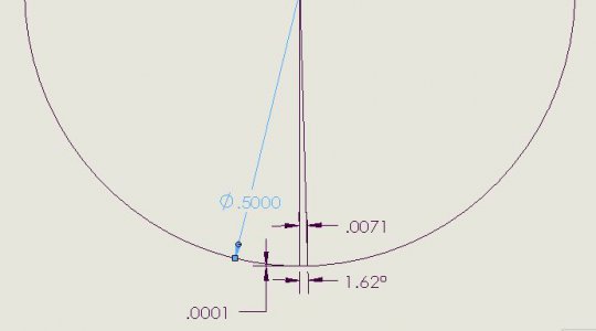
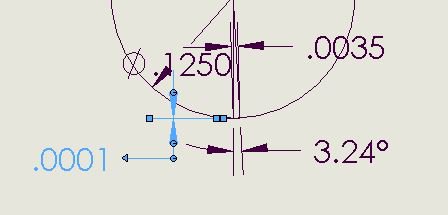
If you put a 1/2" pin in the spindle, a .0001" error in locating the high spot will give you an error of .007" in the X direction and an angular error of 1.6 degrees. Reducing the pin diameter to 1/8" will give you an error of .0035" in the X direction and an angular of 3.2 degrees.I have a Grizzly 1006, which is one of the much maligned round column mill/drills that are sold under various brands. Yes, I want a knee mill, but for right now, this will have to do. Much of the whining about the round column is having to try to return to the head to center after raising or lowering it. I rarely have to move the head, but if I do, I have found a very simple way to check it. I set a dial indicator on the vise and rest the pointer on the round spindle end. I move the head side to side until I find the highest point. The head should now be exactly perpendicular to the bed. This only takes about 2-3 minutes to accomplish and seems to work well. At least it works for me.
Another method would be measure the deviation in the X direction before and after the head adjust. If you have your head set close to perpendicular to start, there is essentially no error in the Y direction and the X direction error is as close as you can set it. It does rely on your head being trammed properly as you are measuring at two different quill extensions. Also, if you have spindle runout, that has to be accounted for.
In either method, use care in tightening the head and recheck the setting when done.


- Joined
- Feb 1, 2015
- Messages
- 9,602
The intent was not to belittle your method but to point out the possible errors you could encounter.I figured someone would tell me my method was flawed.As noted, it works for my purposes.
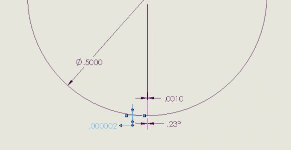
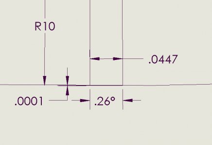
My analysis was flawed as well. The diameter should have been twice the distance from the spindle center line to the column centerline plus the pin diameter. However, that just worsens the X error.
I have owned a round column mill/drill for more than thirty years and struggled with the same problem that you have been. There is really not a good answer. One solution that I had used was to use collets instead of a chuck for drills. This helped to keep the tool lengths more consistent and reduce the need for resetting the column height. For cases where that wasn't sufficient, running a drill or dowel pin into a previously located hole and tightening the column got me fairly close.
The best method would be to re-indicate a reference on the table and readjust your coordinates.
Here is the corrected analysis:

.
I was in no way offended. If it worked well, someone else would have already thought of it. Everything I do is pretty much square, so it really doesn't matter if the head is off perpendicular. The table still travels in a straight line, and I get a new zero for the Z axis just about every time. If the head were at a 30* angle, my work would come out the same, I'd just be working closer to the column. At least that's how it seems to me.
[QUOTE="RJSakowski, post: 306693, For cases where that wasn't sufficient, running a drill or dowel pin into a previously located hole and tightening the column got me fairly close.
.[/QUOTE]
I frequently use this same method. Works well on the mill, and to a little lessor extent works ok on the drill press as well. I recently trammed the mill, and to my amazement everything was within .0005. Needless to say, I left it alone. I installed a new Shars 690v vise and trammed it as well. Still within .001 or less all around. I had been using a cheaper Shars vise, and it became readily apparent that it was off quite a bit. It would have taken a lot of shimming to get it even close. I check the drill press now and then. It seems to stay within a couple of thou. That's probably all I can ask for from a that rig.
- Joined
- Feb 1, 2015
- Messages
- 9,602
Another method that works quite well for small parts held in the vise is to mount the jaws with the vise jaws parallel to the X axis. The head shou;d be perpendicular to the X axis. Adjust the head to approximately the right position and loosen the part in the vise. Now lower the quill with a drill or dowel pin mounted in the spindle into the part and tighten the vise. Since the Y coordinate is relatively insensitive to slight head rotation when the head is perpendicular, any change should be insignificant. The X position will center itself.
If the Y position is unknown, a variation on the above can used. Move the Y feed so the fixed jaw does not quite contact the part and lower a dowel pin or drill into a hole in the part. Close the movable jaw to contact the part. move the Y feed to contact the part. Gradually tighten the vise and readjust the Y position to keep the [part centered between the jaws. Check for binding by raising and lowering the quill slightly. Continue until the part is secured in the vise. You should be very close to centerd.
I use these methods when I'm not working to tight tolerances. You should be able to get within +/- .010" easily and with care +/-.005" or better. As stated before, when accuracy matters, re-indicate.
- Joined
- May 4, 2015
- Messages
- 3,583
Wouldn't clamping a piece of oh 1/2" x 1/2" angle iron rigidly to the base of the column vertically, and then an indicator on the head so if you move up and down you only have to hold zero ? I know it has to be done straight the first time to keep it aligned with the column. Once installed it could stay there . The indicator could be a magnetic and used when needed. Just thinking putting out there see what others have to say.

