Rotary table project

mickri

H-M Supporter - Diamond Member
H-M Lifetime Diamond Member
Joined
Oct 31, 2016
Messages
2,643
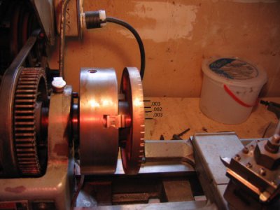
I need a rotary table. My lathe came with a fixture that could be secured to a milling table that was threaded to accept a lathe chuck. I thought that this could be the basis for a rotary table. Any of my lathe chucks or backing plates can be mounted on this fixture. A picture of it mounted in my Craftsman 12x36 lathe is attached. I don't want to take it out of the chuck because I will loose my reference. So I apologize for not having a better picture of it. The lathe has an indexing feature with 60 holes equally spaced around one of the gears. So I chucked the fixture in my lathe and proceeded to scribe marks using the indexing feature around the outside diameter of the fixture. The marks were just over .300 apart. When I got all the way around the last mark was just over .200 from the first mark. A picture is attached. I thought with the indexing feature on my lathe the marks should have been properly spaced around the outside diameter of the fixture. I checked the run out on the fixture in the chuck and the run out is .006. I don't know if that has any bearing on this.
The only two things that I can think of that might have caused this is 1) I didn't have the fixture tight enough in the chuck and each time I scribed a mark the fixture moved an infinitesimal amount or 2) the chuck was not tight enough on the lathe spindle and moved every time I scribed a mark.
Any ideas on what caused this?
Chuck
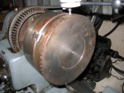
IMG_3407.JPG

IMG_3411.JPG
 
I would guess that your indexing stop setup moved while you were doing the indexing.
 
The indexing feature is built into the lathe. There is a pin on the lathe that you engage into a gear on the headstock that has 60 equally spaced holes in it You can see the holes in the gear in the photo. So I don't know where there could have been a stop that moved.
 
If you want to spend the time you could measure each scribed mark, and see if they are all uniformly spaced or is 1, (or more) out by some amount. Might help you to identify if its slippage or sloppiness in the indexing holes

Cheers Phil
 
It is important in indexing to do each advance to the next position exactly like all the others, and to keep all the backlash from affecting the results by always taking any play out in the same direction using the same technique for each advance. Still, that would only affect individual holes in your case, and only by the amount of play in each indexed hole and pin combination. Did you look at the hole spacing in the gear to look for any that were done wrong? If the first hole was moved clockwise into position, and then all the others were moved counter clockwise into position, the change to the opposite backlash might have been enough to cause your problem.
 
Thanks for all of the suggestions. I after taking countless measurements and trying to figure out what the distance should be between each mark and getting nowhere in figuring out where the error occurred, I decided to start over. First I got the chuck as tight as I could get it on the spindle. Next using my original first mark as a reference point I tightened the fixture in the chuck as tight as I could get it. I then started re-scribing each mark. Within 10 marks it was apparent that the new marks were closer together and closer to my starting mark. I didn't re-scribe each mark. Rather I jumped first to the 20th mark and then to the 40th mark and re-scribed those marks. These new marks were also closer to the starting mark. Finally I re-scribed the 60th mark. It was now where it should be. Tomorrow I will touch up the edge to get rid of the marks I made today and start over making new marks.
What I learned from this is that even if you don't think that you are putting much force on the work piece you really are and you need to have the chuck and the work held as tightly as you can get it.
Chuck
 
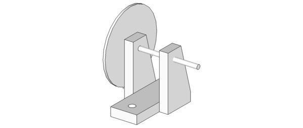
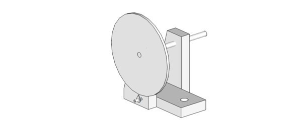
I will need a gear for my rotary table. I also will need other gears to be able to machine metric threads on my lathe. I could always buy the gears but that would not help me learn how to machine. Not having a rotary table or a dividing head is a problem. I searched the internet and found several ideas on how others had solved the problem making gears without a dividing head or rotary table. Using what I had found I started drawing a gear cutting fixture with google sketchup. I really like google sketchup. I find it very easy to create 3D drawings of just about anything. This is my latest idea for a gear cutting fixture. I will make a wood model to see how it fits on my mill/drill. It should also fit on my lathe held in the milling attachment. I haven't decided yet how I will hold the gear to the shaft or how I will lock the shaft in place.
gear fixture 001.jpg

gear fixture 002.jpg


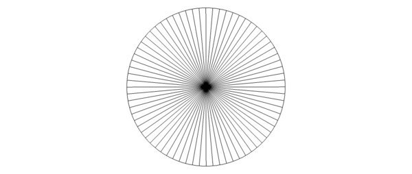
One useful feature of sketchup is that you can easily divide a circle into any number of equally spaced lines. As an example attached is an 8" circle divided into 72 lines. Took only a couple of minutes to do the drawing.

72 circle.jpg

I would print out the divided circle and use double stick tape or spray adhesive to attach it to the circular plate on the fixture. Because of the size of the circle even if you are off center a smidgen the gear will still come out OK. I plan to have a sharp point on center on the circular plate to help position the paper circle.

So what do you guys think of my idea for a gear cutting fixture?
Chuck
 
Print and add a vernier scale as well, which will also allow coarser and easier to read primary divisions. Start with a hole in the center and a single hole near the periphery. Then add other holes measured or indexed from the first. Do some geometric dividing with dividers for a reality check.

Edit: Actually, I would not open up the center hole from a tiny center punch mark until the primary layout is done, to help attain and preserve accuracy as you go.
 
Probably the best way to do it would be to make a worm and worm wheel. A hob would need to be made to get started, I guess. That would be the accurate and correct way to do it, especially if you plan to make gears, where you will need the accuracy.
 
Thanks Bob for reminding me that I need a worm and worm gear to rotate the table. Cold rainy day here. Well cold for California and my garage shop is not heated. So I spend the day tending the wood stove and reading up on worms and worm gears.
Before I can move forward with this project there are decisions to make. Specifically how far to advance the table with one complete turn of the handwheel. This dictates the gearing. I first looked at having a 36 tooth worm gear turned by a 10 TPI worm. This would make the table advance 10 degrees with each full turn of the handwheel. 36 turns for a full revolution of the table. The hand wheel could be divided into 100 marks and life would be good. But when I checked the size of a 36 tooth worm gear I discovered that it is to small in diameter to work for me. The bore on the worm gear has to be 1.5 inches. So the minimum outer diameter of the worm gear has to be around 2.25 inches. I would have to use a worm with 4 or 5 TPI. This is a pretty coarse thread and I don't know how hard it would be to cut this thread or if it would even work with a worm gear.
Next I tried a 72 tooth worm gear with a 10 TPI worm. This is still a pretty small gear but would work. If I did the math correctly this gear would 2.355 inches in diameter. I just think that a larger diameter gear would work better. I have nothing to support this. If I used a worm with 8 TPI the diameter would be 2.944 inches. I could live with this. With a 72 tooth worm gear one full turn of the handwheel would advance the table 5 degrees. This would not be as convenient as a 10 degree advance. The handwheel would have 50 marks and would be a direct reading from 10 to 15 degrees for example but I would have to remember to add 5 degrees for readings from 15 to 20 degrees. Any other division of 360 degrees is just too convoluted. The only other convenient division is a 360 tooth worm gear. But who wants to have to turn the handwheel 360 times to make one full revolution of the table. 72 is bad enough.
My understanding of the math to calculate the outer diameter is Diameter=#teeth+2/(TPI x 3.1416).
Am I missing something or have I calculated it correctly?
Chuck
 
Back
Top