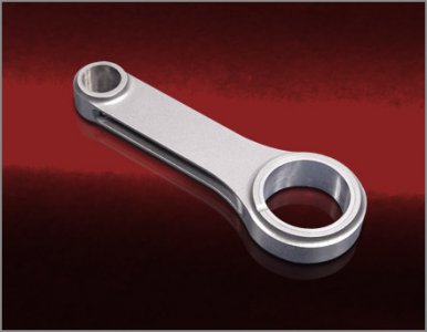
I just purchased a Phase II 10" rotary table from Enco for my Bridgeport mill. I'm trying to build a connecting rod similar to the one pictured below except no fluting and straigth sides from large diameter from large diameter to small diameter and completely flat. The connecting rod is part of a Planishing Hammer and does not have to be as accurate as a connecting rod for an engine. It will be made from 3/4" 6061-T6 aluminum plate. This is my first experience with a rotary table and would appreciate some advice as to how to build this part. My idea would be to center one of the ends over the center of the table with one of the sides parallel with the mill table. The table has a Morse Taper 3 hole in it but the hole is not a through hole. I'd like to know how the MT3 hole in the table should be utilized. Thanks in advance for your help.View attachment 35453
Hello Fergi
I notice this is your first post, wellcome to the forum.

Reading your general plan sounds fine, But your going to need to make up some of your own tooling to get started. I allso noticed you have just purchased the rotary table. To start with, you should machine up some T-nuts to fit your table. Usually I drill and tap the T-nuts for 2 different sizes of threads. Depending on the length, you could go 3 or4. The next thing I would go after is the MT for the centre hole. You could make one, or take a existing one and mod it to suite. The the easy way to get started would be take a MT and cut the top end flush with your table, and drill and tap for a hold down bolt. The bottom end, drill and tap as well, and also make a plug for the back of the table to draw your MT into it, and ensure the MT is locked in position, and stays there.
Once you get these things done, you only have the foundation for bolting things to your table. With R/T work, you will find that job after job, you will be making up bits and pieces to aid your work holding issues. I have all kinds of different things to get me through several jobs. I thing that comes to mind, that seems to ge alot of use, is those elcheapo bearing driver kits. They have several OD sizes in the kit, and half of each one is tapered. These help when trying to hold a item such as a con rod down by the bore to profile the sides.
With R/T work, there is a never ending job of making spacers , arbours, and just odd widgits to mount your work down solid to allow you to machine it. Work holding on the R/T can be a challenge. Just take each work holding job and deal with it one at a time. Save the bits you use to mount your work, it wont take long before you have a drawer full of usefull things to help with the next job.


