Rotary Phase converter problem

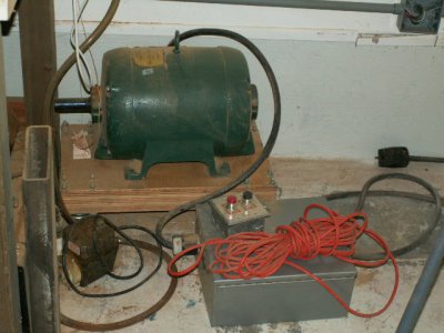
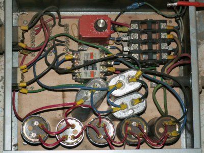
It looks/sounds like your RPC doesn't have any balancing capacitors. A lot of RPC's are made this way and run for many years without any issues to the RPC or the 3ph motors being powered.

Are you measuring the voltages when the RPC is powering a 3ph motor? Do they change when the powered motor is under load? The current readings on each leg are much more meaningful if you have a clamp on amp meter?

Bottom line is you really don't have anything to worry about.
 
I now have a 100 uf capacitor between 3+2 and a 55 uf between 3+1 voltages are now as follows while running a 1 HP bridgeport with a large flycutter with the pulley in the highest speed no cutting.

1+2 = 248
2+3 = 250
3+1 = 251

The largest motor I own is only 3hp and I never run more than 1 machine at a time.

The original design of this RPC had an estimated 150 or 200 uf between 2+3 and nothing between 1+3. Without the 55 uf between 1+3 the voltage with the bridgeport running

1+2 = 246
2+3 = 231
3+1 = 248

Adding an additional 100 uf. (200uf) resulted in

1+2 = 246
2+3 = 258
3+1 = 276


Thanks for the help, it helped me understand this very abstract concept. I still can't figure out how I get an additional 15 volts on each leg, If I wanted to run a 208 motor, is there a practical way to drop the voltage a little?
 
A three phase transformer would do the trick, although finding an affordable one to go from 240 to 208 would be tough. You could always wind your own if you are up to the challenge.
 
I now have a 100 uf capacitor between 3+2 and a 55 uf between 3+1 voltages are now as follows while running a 1 HP bridgeport with a large flycutter with the pulley in the highest speed no cutting.

1+2 = 248
2+3 = 250
3+1 = 251

The largest motor I own is only 3hp and I never run more than 1 machine at a time.

The original design of this RPC had an estimated 150 or 200 uf between 2+3 and nothing between 1+3. Without the 55 uf between 1+3 the voltage with the bridgeport running

1+2 = 246
2+3 = 231
3+1 = 248

Adding an additional 100 uf. (200uf) resulted in

1+2 = 246
2+3 = 258
3+1 = 276


Thanks for the help, it helped me understand this very abstract concept. I still can't figure out how I get an additional 15 volts on each leg, If I wanted to run a 208 motor, is there a practical way to drop the voltage a little?

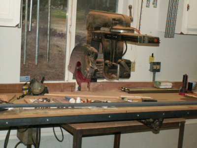
I have been running a 208v 7.5hp radial arm saw motor on my 10hp RPC for near 30 years with voltages higher than yours. You are overthinking things! You can run a 208v motor with the voltages you have currently. No need for a transformer! If you are really worried use a clamp on amp meter to see how much current each leg is pulling. Excessive current will heat up the windings and melt the insulation... not excessive voltage.

My 7.5hp RAS is a 1947 Redstar... back then wire insulation wasn't nearly as advanced and heat resistant as it is in modern motors. A modern 3ph motor will have no issue at all with the voltages you are showing.
 
I just finished replacing the bearings and tidying up everything. It is now very quiet and the voltages seem ok. What started me looking at this was the fact that the two spare 3 phase motors that i have show very different amperages on each leg. I will have to hook them up and test them to see if there is any difference.

Thanks again for all the advice.

JD

I built my 10hp RPC 30 or so years ago to power my pretty rare 1947 RAS with a 3ph motor custom designed to hold and swing a 16" saw blade (there is really no way to replace it)... I had the EXACT same concerns then that you are having now! I hope I was able to mitigate some of your concerns a bit. :)

PICT8057.JPG

PICT8058.JPG

PICT8052.JPG
 
Last edited:
Back
Top