Reversing Switch And Controller Protection

grantj

Registered
Registered
Joined
Jun 22, 2015
Messages
30
Hi all, sorry, I have very little experience with electrical circuits.

I want to add a Motor Reverse switch (DPDT) to the Harbor Freight mini mill spindle.
But from what I've read, if the spindle is still turning, when the power is off, the motor acts like a generator and produces current.

If I want to protect the control board from burning up, would this set up work? Adding two diodes before the motor and switch, so that current could not flow back into the board?

Thank you!
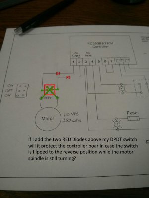
IMG_20150727_142429.jpg
 
Last edited:
Does your motor have permanent magnets instead of stator windings? That would be necessary to be able to reverse the motor as you have it drawn. If the motor is a universal motor (ac/dc) then your circuit won't work.

Assuming a PM motor, A permanent magnet dc motor will act as a generator while it is turning. When your controller is turned from full rpm to zero, the back voltage will be applied to the controller as the motor winds down and the controller should be able to handle it. Diodes aren't necessary.

When you reverse the controller voltage with your added switch, the generated voltage it will be assisting rather than bucking the applied voltage which should cause an increased current draw until the motor comes to a stop and reverses direction. That may be more current than your controller can handle.
 
Its the stock motor that comes with the Harbor Freight mill, I believe it is permanent magnets.

I'm still not sure I understand what I should do then. I had an electronics class many years ago, but it was unfortunately more math based than practical application.
 
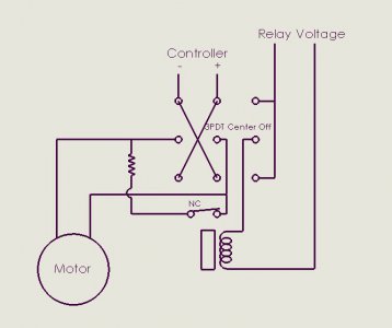
I think you can accomplish your objective with some relays. Basically, what you need to do is to short the motor windings when you remove applied power. This will sink the rotational energy from the motor, acting as a brake. Depending on the resistance of the short, the motor can be stopped in a very short period of time. The motor can then be safely reversed. I am pondering as how to accomplish this.

Were it not for the varying control voltage, it would be fairly simple. A normally closed relay wired across the motor leads which would open whenever controller voltage were applied. It might be simpler to throw some electronics into the mix. A controller voltage sensor that would be able to handle the variation in controller voltage swing and energize the shorting relay to remove the short. If your controller is using pulse width modulation to vary the motor speed (and it should as you get better low end torque and control), there may be enough of a signal to energize a relay.

The contacts of the relay should be able to handle the maximum run current of the motor.

I'll get back to you when I figure it out.

Bob
 
OK, Here it is.

The relay is powered by some source, e.g. line voltage, etc. The dpdt switch in your circuit is changed to a 3pdt, center off switch. In the center position, the relay is de-energized and the contacts are closed. This inserts the resistance across the motor windings shorting it out and braking the motor in the process. The resistance can actually be 0 ohms or it can be some low value ohms. The higher the resistance, the longer it will take to dissipate the motor rotational energy. When the switch is toggled in either direction, voltage is applied to the relay coil and the contacts open. At he same time, voltage is applied to the motor and the motor rotates, its direction dependent upon which direction the switch is toggled and the speed determined by the controller setting. Flipping the switch to the center position removes the controller voltage and shorts out the motor again.

You may want to check to see how comfortable your controller is with suddenly opening its circuit. There may be some transients created. Clamping diode or snubbers may help.

I actually run a reversing system on my old electric trolling motor where the current can exceed 40 amps. It is a pulse width modulation circuit. I don't use a shorting mechanism but I also drop the controller setting to a very lowvalue before switching. I do so primarily to avoid burning the reversing switch contacts: It is a royal pain to change that switch. :eek:
Check it out. No guarantees that my logic is correct. I've been known to be wrong before (ask my wife) ;).

Bob
Motor Reversing Circuit.JPG
 
wow Bob, thanks for the help.
Give me a few to try and understand this and find the right components.

I appreciate the help a lot.
 
wow Bob, thanks for the help.
Give me a few to try and understand this and find the right components.

I appreciate the help a lot.
Here are You can power the relay directly off the 110 vac line (after your main switch and fusing). If you have a low voltage supply in the mill, you can power the relay from that.
The switch contacts are not rated for d.c. current but given that you would not be likely to throw the switch from forward to reverse at full speed very often, if ever, that shouldn't be a problem. Same thing for the relay contacts. If you use a resistor, it would probably be a low ohm wirewound. Because of the momentary nature of the current flow, you should not need much in the way of wattage. I would guess that 5 or 10 watts would be sufficient.

The suggested use would be to dial down your controller before switching, then flip the switch to the center position until the spindle stops, then switch to the other direction and dial up the controller. This will present the least chance of any wear due to arcing. The circuit should be able to handle a full speed reversing but it is hard electrically and mechanically. If you were looking at using this for threading, you would be rotating at a low enough speed that you should be able to go into reverse without a problem.

Here is a 110 vac relay candidate:
http://www.digikey.com/product-detail/en/G2R-1-S AC120(S)/Z1635-ND/585511
Here are some switch candidates:
http://www.digikey.com/product-detail/en/HM254-73/432-1268-ND/3025033
http://www.digikey.com/product-detail/en/ET310E12-Z/563-1908-ND/5086812
 
Most of the above suggestions seem reasonable, but I would think twice before shorting the motor windings while they are still in rotational mode and producing voltage. You cold damage your windings and/or other wiring components in the motor itself, not to mention the shorted contactor. Safer and easier on components to switch the motor to a resistor bank to slow the motor quickly and safely.

Bob
 
I have an HF mini-mill. Added a DPDT reversing switch about 1 1/2 years ago, for use when power tapping. I use an aftermarket (LMS) belt drive, which limits torque somewhat. But I can easily go up to #10 in aluminum.

I run the motor as slowly as I can during tapping, and have not had any problems flipping the switch and reversing the motor while it's running. I would NOT try reversing the motor at any speed above very slow, for the reasons you and others have pointed out.

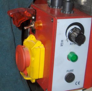
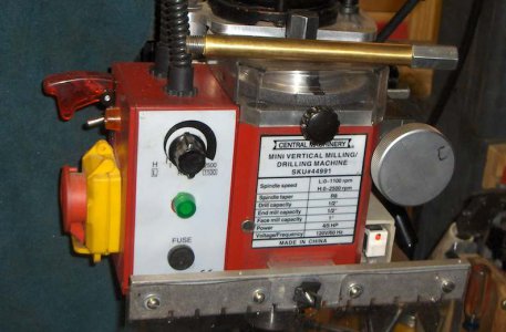
The first photo shows my switch, with a “safety cover” I got from Radio Shack before they closed. Closing the cover assures that the switch is down and motor is turning the right way when I’m milling. The second photo shows an extended drawbar I cobbled up. This allows the chuck to “float” up and down with the tap as it’s threading its way into and out of the hole. The R-8 pin drives the chuck.
kHPIM3838.jpg kHPIM3840.jpg
 
Back
Top