Quick Measurement Of Small Taper Angle

randyc

Active User
Registered
Joined
Feb 5, 2015
Messages
662
I'm re-posting a quick suggestion that I made on another forum regarding measuring taper angles.
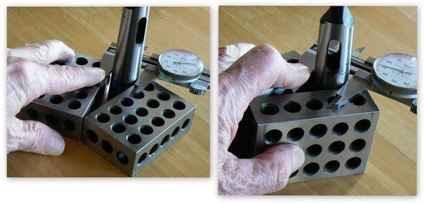
2015-03-25_zpseh2ojxd7.jpg

Simple way to measure small tapers. Place the taper between 1-2-3 blocks and measure diameter across the 1 inch surfaces with calipers, making sure that the calipers are flat against the blocks. Repeat measurement across 2 inch surfaces. Subtract the smallest diameter from the largest and divide the result by two. The angle of ONE side of the taper is the arc-tangent of this number. (Do this on a surface plate, not the kitchen table, LOL).

Example: The measured diameter with calipers resting on 1 inch surface is .745. Measured diameter with calipers on 2 inch surface is .620.

(.745 - .620) / 2 = .0625 and arc-tangent(.0625) = 3.5763 degrees or 3 deg 34 min 35 sec

For the included angle of the taper, double this result.

You can also use the 1 inch and 3 inch surfaces of the 1-2-3 blocks to gain a bit more accuracy. If you do this, however divide the difference between the diameters by "4" instead of "2".
 
And in your exsample that is a 1 in 16 taper.[ 1" in 16"] Witch is the easeyest way to set up to cut a taper on a lathe. If I don't have a dro on the lathe I use 2 dial indicators to set the compound or taper atachment. That is the most common taper used. Besides the MT, tape it is a marine taper and pipe taper anmost tapered pins.
 
Last edited:
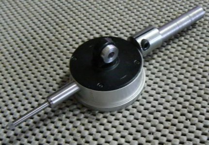
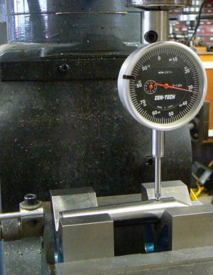
I just thought of another easy way to measure a taper. I made this simple tool some years ago for measuring shallow angles in a vertical milling machine vise, as shown below.

P1010431.jpg

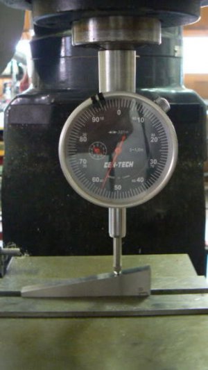
Either setting or measuring the taper involves moving the table a precise, known distance and measuring the "rise" with the travel indicator. Use arc-tangent to either determine the measured angle or to tap the workpiece until the rise is the correct tangent (if milling the angle.)


P1010425.jpg

Works good for measuring tapers, too:

P1040970_zpspsekodxs.jpg

NOTE: the indicator must be exactly centered on the taper centerline.
 
Last edited:
If you have digital readouts on your mill it gets even easier. Put a dti in the spindle, carefully align it with the taper centerline and zero it on the large diameter of the taper. Crank the "X" axis until the dti is near the small end of the taper. Carefully raise the "Z" axis until the dti is zeroed again. Take a look at the DRO: the arc-tangent of the distance the "X" axis traveled divided by the distance the "Z" axis traveled is the included angle of the taper.
 
If you have digital readouts on your mill it gets even easier. Put a dti in the spindle, carefully align it with the taper centerline and zero it on the large diameter of the taper. Crank the "X" axis until the dti is near the small end of the taper. Carefully raise the "Z" axis until the dti is zeroed again. Take a look at the DRO: the arc-tangent of the distance the "X" axis traveled divided by the distance the "Z" axis traveled is the included angle of the taper.
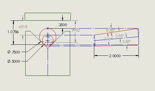
I believe that your calculation is over simplified. Because of the smaller diameter on the small end measurement, it sits lower in the vee block than the large end. As a result, the bottom surface is not horizontal. Neither is the centerline of the taper. To illustrate, the drawing below shows a taper of 1/8"/"resting in a vee block with measurements made 2 inches apart. The projection to the right shows how the taper is inclined and shows a measured angle of 8.50degrees instead of the actual 7.10 degrees.
It is possible to measure the taper with this setup but the math gets more complicated. I find the easiest way to do this is with a CAD package. The illustration was done in Solidworks and by making the right dimensions driven, the drawing will spit out the angle. I expect that other CAD programs can do similar calculations. Gotta love those CAD programs!
Vee Block Taper Measurement.JPG
 
I believe that your calculation is over simplified. Because of the smaller diameter on the small end measurement, it sits lower in the vee block than the large end. As a result, the bottom surface is not horizontal. Neither is the centerline of the taper. To illustrate, the drawing below shows a taper of 1/8"/"resting in a vee block with measurements made 2 inches apart. The projection to the right shows how the taper is inclined and shows a measured angle of 8.50degrees instead of the actual 7.10 degrees.
It is possible to measure the taper with this setup but the math gets more complicated. I find the easiest way to do this is with a CAD package. The illustration was done in Solidworks and by making the right dimensions driven, the drawing will spit out the angle. I expect that other CAD programs can do similar calculations. Gotta love those CAD programs!
View attachment 98663

You're right. I assumed that for small tapers the error would be negligible. The taper must sit on a flat surface which leads to the problem of how to hold the taper in the mill vise so that its axis is aligned with the table travel (necessary for accurate measurement).

This detracts from the simplicity of the procedure, LOL, leading to such "fixes" as holding the taper in place with modeling clay and the like. If one cared to make a simple alignment tool, however, the measurement would still be quick and simple.

Oops can't attach to an edit will have to make a new post.
 
Last edited:
I started sketching a simple alignment tool but it turned out NOT to be so simple. I couldn't justify making a tool to align the taper when I might measure a taper every two years or so, LOL. I think I'd better forget this method (unless someone can come up with a simple centering technique) and go back to the 1-2-3 block procedure :)

P.S. Thanks for pointing this out !
 
You're right. I assumed that for small tapers the error would be negligible. The taper must sit on a flat surface which leads to the problem of how to hold the taper in the mill vise so that its axis is aligned with the table travel (necessary for accurate measurement).

This detracts from the simplicity of the procedure, LOL, leading to such "fixes" as holding the taper in place with modeling clay and the like. If one cared to make a simple alignment tool, however, the measurement would still be quick and simple.
Randy, It still is a useful technique and now I have a SolidWorks tool that makes the calculation easy. It goes into my bag of tricks! For those not fortunate enough to have access to SolidWorks or a similar CAD program, it could be set up as a Excel spreadsheet. Input the separation distance between the two z axis measurements and the two z axis measurements and it will spit out the taper angle. The beauty of your technique is the type of contact point doesn't matter since the same angle conditions exist for either measurement; just like a sine bar.

The one issue that I have with methods like this is the relatively small difference in the two z measurements. Typical measurement errors can cause a fairly large error in the resulting taper calculation. The Tormach DRO is capable of resolving .0001" and my digital indicator will resolve .00005" which means each measurement could deviate from actual by .00015" Since I am making two measurements, my error could be as much as .0003" Over a two inch span, this would be an error of about .5 min. of angle. From what I was able to glean in some earlier work, the AT2 std. for taper manufacturing is about 1/10th that tolerance. (ISO-1947 is, I believe, the defining document). If I were trying to make a Morse taper tool, I don't believe I would be able to determine whether it was satisfactory or not.
 
....From what I was able to glean in some earlier work, the AT2 std. for taper manufacturing is about 1/10th that tolerance. (ISO-1947 is, I believe, the defining document). If I were trying to make a Morse taper tool, I don't believe I would be able to determine whether it was satisfactory or not.

That is ASTOUNDING, I had no idea the tolerance was that strict and I'd bet that most machinists with decades of experience would not know !!! I've made a number of Morse taper tools - not scores by any means but probably a dozen, using either compound or taper attachment. In both methods I (and everyone else that I know) set up for taper turning by indicating a known good taper and adjusting the setup until there is no discernible error shown on the DTI.

After turning the taper, the normal fit check (as we all know) is to blue the part and check against a known good female taper. If there is variance, the high spots can be carefully removed with file and sandpaper until a good fit is obtained. I can't imagine that most small machine shops (much less the HSM) have the capability to measure angular error at the limit you mention.

I have to shake my head at that standard and consider the millions of tapers that have been turned by the hundreds of thousands of craftsmen over the decades - all were likely functional to the intended purpose. I wonder if even one machinist in a thousand attempted to set up their machine to a taper standard.

(Incidentally, a few imported morse taper adapters can be useful for checking fit. They are inexpensive and each one can serve as both a male and a female fit check. The first photos in this post depict one of these adaptors, a MT-3 male to MT-2 female. There is the risk, however, of dimensional variation.

We're fortunate in that we don't need to give much emphasis to interchangeability. If we find a particular tool that well fits the lathe tailstock, as an example, then that tool becomes the standard for making any new tooling for the tailstock.)
The key is in your second paragraph. You are essentially hand finishing to final fit. It's actually a very sensitive technique. The amount of material removed would be quite small. Unfortunately, it requires a known good taper.
When you think about it, a proper taper has to wring to its mate in order to provide the necessary amount of friction to drive a tool.
 
Back
Top