- Joined
- Feb 5, 2015
- Messages
- 662
(This post describes a repair procedure performed on a broken knee-mill crank some time ago. I photographed parts of the "fix" but unhappily the old digital camera didn't focus very well at close range, sorry.)
I bought a Taiwanese 8 x 30 vertical mill a dozen years ago and the machine has been useful for small, non-ferrous work, the reason that it was purchased. Now that I have retired, it is used almost exclusively on ferrous parts and it's kind of "rubbery" for this work. The knee crank on the machine was broken within days of delivery due to my clumsiness during a move.
The price for the cast-iron replacement part that the distributor (Enco) quoted was unacceptable so I didn't buy one. I cleaned and brazed the crank together. All went well for about five years until the crank separated at the brazed joint. I repeated the fix … which separated again six years later.
I ran out of oxygen while attempting to braze it the last time … and of course this occurred late Friday afternoon and the oxygen supplier is fifteen miles away. This seems to be typical of most of my "emergencies". Options were limited - the brazing "fix" obviously wasn't a permanent one (I'm blaming the unknown casting material rather than my lack of skill, ha-ha). Although I have a couple of MIG welders, I no longer have a stick welder so couldn't use a nickel rod EVEN if I had the gas for the pre-heat.
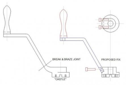
I'd have to wait until Monday morning to refill my tanks and I wanted a quicker repair … I don't remember why since I'm retired and nothing much is on a schedule. Here's what I came up with, but note that the CAD drawing was made AFTER the repair, the sketch that I actually worked from was not fit to post here.
When I modify something I try to document it and place a copy of the modification in the manual. I don't always remember but I did this time. (I do this partly because my memory isn't so good but also because a full and careful set of documentation enhances the value of an item when it's time to sell it.)
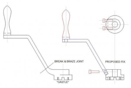
Obviously, my solution was to machine the two parts to mate then bolt them together. A problem was that the cross-section doesn't allow large fasteners to secure the broken crank to the "castle" coupling. Also, the constant raising/lowering of the estimated 400 pound knee would be sure to loosen the fasteners if they are required to withstand rotational torque.
My thinking was that a vee-joint would be helpful. There was enough space for a pair of 1/4-20 socket head cap screws to secure the two parts. If the two fasteners are located along the axis that "locks-up" the vee, then the vee transmits the torque instead of the screws. The two cap screws are loaded only axially and the joint should be solid.
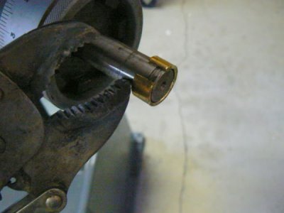
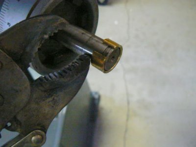
Oh yeah, before I forget - I needed to use the mill to modify the parts but had no crank to raise/lower the knee since this occurred before I bought my second mill. Happily that was a simple fix - split a brass bushing and clamp over the pin with a large pair of vise grips to rotate. Awkward, takes a long time to move the knee but acceptable until the crank is repaired.
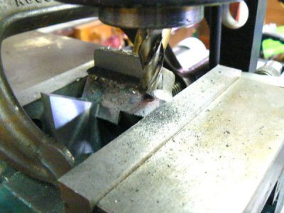
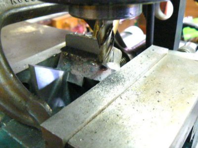
The vee in the cast-iron castle needs to be cut with reasonable accuracy and the setup needs to be stable. Can't just put a rounded, rough casting into the milling vise, prop it up at a 30 degree angle and assume that the angle plate will stay put during the milling operation. After clamping the castle in the milling vise, resting on a 30 degree angle plate, the angle plate was prevented from slipping out from under the castle with a C-clamp (securing the plate to the castle).
Next, a brass bushing, turned to fit and inserted into the crank pin bore, provided a solid surface on which a step clamp could apply vertical pressure to the castle. The setup for this part could be implemented in many different ways so long as every axis of movement is constrained. (It's not easy to see the bushing in the photo of the set-up below - cramped quarters, poor lighting and poor focus.)
As we know, coolant isn't a good idea for cast-iron so I used a shop vacuum to suck up the chips while cutting (cleaning the machine thoroughly after machining cast iron is absolutely necessary). After the setup was secure, a four-flute end mill produced the required configuration (spindle RPM set to about 70% of the speed that one would normally use for mild steel).
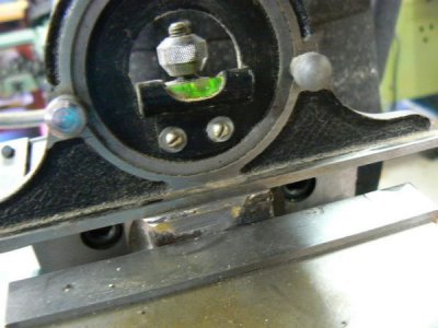
Before drilling the mounting holes, the castle needs to be aligned in the mill so that the vee is perpendicular to the mill spindle. There are many setup possibilities and the spirit level in the protractor head of a machinist's square suggests a quick one - it is not a high precision method but is more than adequate for my purpose.
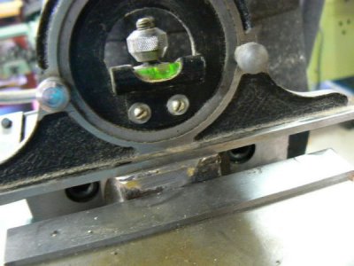
The spirit level was first calibrated by "zero-ing" it when held in the milling vise on parallels. Then the castle was lightly clamped in the mill vise with the level resting in the vee groove previously milled. The castle was lightly tapped with a small brass hammer until level (perpendicular to the spindle). The photo leaves something to be desired but shows the level resting in the vee of the castle which is clamped in the milling vise. As a matter of interest, a good spirit level supplied with a machinist's square will provide measured angular accuracy of around 20 minutes of arc.
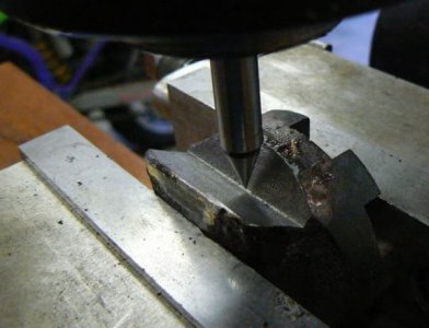
The centerline of the vee needs to be located because the holes will be referenced from the centerline (it's the only readily available machined edge). A conical edge finder is a useful tool for this purpose (older eyes can use the assistance of a toolmaker's microscope or a high-power magnifying glass):
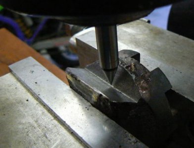
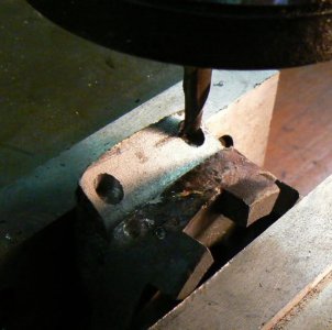
After cranking off the desired offsets, the tapped holes that secure the clamp arm can be produced. As can be seen in the above sketch, the holes aren't perpendicular to the pocket, they are inclined at 30 degrees. We can't easily center drill or tap drill at this angle without the drill skidding off the inclined surface so I first spotfaced the hole locations with a 1/4 diameter end mill, just deep enough so that mounting holes can be centered, drilled and tapped.
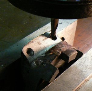
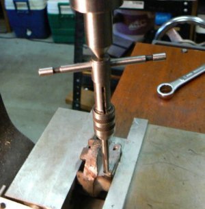
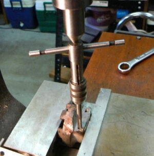
I was a little worried about the casting material (especially considering the poor brazing qualities). I've heard a lot of horror stories about hard spots and foreign material in imported castings. To make the tap drill run true, I used a 2-flute 3/16 solid-carbide end mill to bore a starter hole about 3/4 deep followed by the tap drill before tapping the mounting holes. (The tap wrench is being steadied with a lathe dead center in an R-8/Morse taper adaptor. Any number of similar guides can serve the same purpose.)
The crank arm surfaces mating with the castle need to be milled true (to eliminate the casting draft angle and the rough surface finish). Similar clamping problems exist with this rough, tapered cast part as in the setup described above. The two perpendicular surfaces can be milled in one setup and their angular relationship to the remainder of the cast surfaces isn't critical.
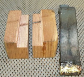
In this situation it's convenient to clamp the part between scraps of wood. The wood, under heavy clamping pressure from the mill vise, will conform closely to the irregular surfaces of the workpiece providing a sturdy and secure temporary platform.
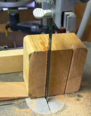
About five minutes were required to produce the cradle shown below. After tracing the outline of the crank on a scrap of 4 x 4, the outlines were cut on a bandsaw - note the use of a tapered scrap of wood to hold the cradle at the proper angle during sawing. (A hot-glue-gun is handy for tacking setup expediencies together temporarily.)
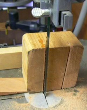
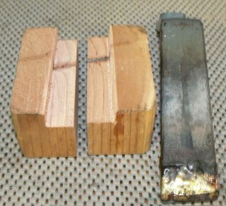
The cradle was cut in half and the bandsaw used again, this time to cut a ledge for the crank to rest on.
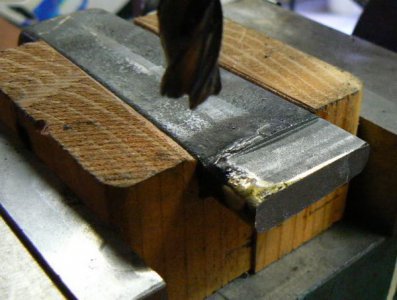
Here's the crank, held tightly in the cradle after two surfaces have been roughed perpendicular to one another. One more horizontal pass and one vertical pass will complete the operation:
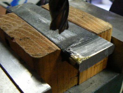
After truing, the crank arm was spotfaced with a 7/16 end mill at the location of the mounting screws to provide a perpendicular surface for drilling the clearance holes and to provide a flat seating surface for the heads of the mounting screws. As when performing one of the previous operations, the crank arm must be oriented 30 degrees from the spindle axis.
(Lacking a spotfacer or counterbore, when spotfacing with an end mill, it's helpful to sort through your collection of mills and find one with the flattest bottom. Most two-flute end mills have angled bottom surfaces while four-flute mills are more likely to be flat.)
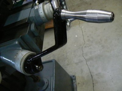
Hardwood scraps were also used in this operation (for their ability to conform to the rough-cast draft angles of the handle) and the angle was again established with the spirit level. Since through holes were required, I didn't want to leave an angle plate permanently in the setup under the workpiece risking collision with a drill. After completing all operations and de-burring, the parts can be securely assembled with the socket head cap screws and here's the finished crank (I painted it a week or two after the fix, after confirming that it functioned satisfactorily - unhappily I had no paint of the correct hue):
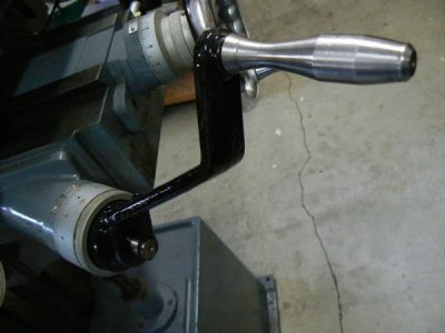
Repairing the crank twice (by brazing) took about five minutes and lasted about five years each time while the machining fix required several hours. I'd have brazed the thing again had I not exhausted the oxygen tank with no refill available until Monday, LOL ! Oh well, this time the fix will outlast me
I bought a Taiwanese 8 x 30 vertical mill a dozen years ago and the machine has been useful for small, non-ferrous work, the reason that it was purchased. Now that I have retired, it is used almost exclusively on ferrous parts and it's kind of "rubbery" for this work. The knee crank on the machine was broken within days of delivery due to my clumsiness during a move.
The price for the cast-iron replacement part that the distributor (Enco) quoted was unacceptable so I didn't buy one. I cleaned and brazed the crank together. All went well for about five years until the crank separated at the brazed joint. I repeated the fix … which separated again six years later.
I ran out of oxygen while attempting to braze it the last time … and of course this occurred late Friday afternoon and the oxygen supplier is fifteen miles away. This seems to be typical of most of my "emergencies". Options were limited - the brazing "fix" obviously wasn't a permanent one (I'm blaming the unknown casting material rather than my lack of skill, ha-ha). Although I have a couple of MIG welders, I no longer have a stick welder so couldn't use a nickel rod EVEN if I had the gas for the pre-heat.
I'd have to wait until Monday morning to refill my tanks and I wanted a quicker repair … I don't remember why since I'm retired and nothing much is on a schedule. Here's what I came up with, but note that the CAD drawing was made AFTER the repair, the sketch that I actually worked from was not fit to post here.
When I modify something I try to document it and place a copy of the modification in the manual. I don't always remember but I did this time. (I do this partly because my memory isn't so good but also because a full and careful set of documentation enhances the value of an item when it's time to sell it.)

Obviously, my solution was to machine the two parts to mate then bolt them together. A problem was that the cross-section doesn't allow large fasteners to secure the broken crank to the "castle" coupling. Also, the constant raising/lowering of the estimated 400 pound knee would be sure to loosen the fasteners if they are required to withstand rotational torque.
My thinking was that a vee-joint would be helpful. There was enough space for a pair of 1/4-20 socket head cap screws to secure the two parts. If the two fasteners are located along the axis that "locks-up" the vee, then the vee transmits the torque instead of the screws. The two cap screws are loaded only axially and the joint should be solid.
Oh yeah, before I forget - I needed to use the mill to modify the parts but had no crank to raise/lower the knee since this occurred before I bought my second mill. Happily that was a simple fix - split a brass bushing and clamp over the pin with a large pair of vise grips to rotate. Awkward, takes a long time to move the knee but acceptable until the crank is repaired.

The vee in the cast-iron castle needs to be cut with reasonable accuracy and the setup needs to be stable. Can't just put a rounded, rough casting into the milling vise, prop it up at a 30 degree angle and assume that the angle plate will stay put during the milling operation. After clamping the castle in the milling vise, resting on a 30 degree angle plate, the angle plate was prevented from slipping out from under the castle with a C-clamp (securing the plate to the castle).
Next, a brass bushing, turned to fit and inserted into the crank pin bore, provided a solid surface on which a step clamp could apply vertical pressure to the castle. The setup for this part could be implemented in many different ways so long as every axis of movement is constrained. (It's not easy to see the bushing in the photo of the set-up below - cramped quarters, poor lighting and poor focus.)
As we know, coolant isn't a good idea for cast-iron so I used a shop vacuum to suck up the chips while cutting (cleaning the machine thoroughly after machining cast iron is absolutely necessary). After the setup was secure, a four-flute end mill produced the required configuration (spindle RPM set to about 70% of the speed that one would normally use for mild steel).

Before drilling the mounting holes, the castle needs to be aligned in the mill so that the vee is perpendicular to the mill spindle. There are many setup possibilities and the spirit level in the protractor head of a machinist's square suggests a quick one - it is not a high precision method but is more than adequate for my purpose.
The spirit level was first calibrated by "zero-ing" it when held in the milling vise on parallels. Then the castle was lightly clamped in the mill vise with the level resting in the vee groove previously milled. The castle was lightly tapped with a small brass hammer until level (perpendicular to the spindle). The photo leaves something to be desired but shows the level resting in the vee of the castle which is clamped in the milling vise. As a matter of interest, a good spirit level supplied with a machinist's square will provide measured angular accuracy of around 20 minutes of arc.

The centerline of the vee needs to be located because the holes will be referenced from the centerline (it's the only readily available machined edge). A conical edge finder is a useful tool for this purpose (older eyes can use the assistance of a toolmaker's microscope or a high-power magnifying glass):

After cranking off the desired offsets, the tapped holes that secure the clamp arm can be produced. As can be seen in the above sketch, the holes aren't perpendicular to the pocket, they are inclined at 30 degrees. We can't easily center drill or tap drill at this angle without the drill skidding off the inclined surface so I first spotfaced the hole locations with a 1/4 diameter end mill, just deep enough so that mounting holes can be centered, drilled and tapped.

I was a little worried about the casting material (especially considering the poor brazing qualities). I've heard a lot of horror stories about hard spots and foreign material in imported castings. To make the tap drill run true, I used a 2-flute 3/16 solid-carbide end mill to bore a starter hole about 3/4 deep followed by the tap drill before tapping the mounting holes. (The tap wrench is being steadied with a lathe dead center in an R-8/Morse taper adaptor. Any number of similar guides can serve the same purpose.)

The crank arm surfaces mating with the castle need to be milled true (to eliminate the casting draft angle and the rough surface finish). Similar clamping problems exist with this rough, tapered cast part as in the setup described above. The two perpendicular surfaces can be milled in one setup and their angular relationship to the remainder of the cast surfaces isn't critical.
In this situation it's convenient to clamp the part between scraps of wood. The wood, under heavy clamping pressure from the mill vise, will conform closely to the irregular surfaces of the workpiece providing a sturdy and secure temporary platform.
About five minutes were required to produce the cradle shown below. After tracing the outline of the crank on a scrap of 4 x 4, the outlines were cut on a bandsaw - note the use of a tapered scrap of wood to hold the cradle at the proper angle during sawing. (A hot-glue-gun is handy for tacking setup expediencies together temporarily.)

The cradle was cut in half and the bandsaw used again, this time to cut a ledge for the crank to rest on.

Here's the crank, held tightly in the cradle after two surfaces have been roughed perpendicular to one another. One more horizontal pass and one vertical pass will complete the operation:

After truing, the crank arm was spotfaced with a 7/16 end mill at the location of the mounting screws to provide a perpendicular surface for drilling the clearance holes and to provide a flat seating surface for the heads of the mounting screws. As when performing one of the previous operations, the crank arm must be oriented 30 degrees from the spindle axis.
(Lacking a spotfacer or counterbore, when spotfacing with an end mill, it's helpful to sort through your collection of mills and find one with the flattest bottom. Most two-flute end mills have angled bottom surfaces while four-flute mills are more likely to be flat.)
Hardwood scraps were also used in this operation (for their ability to conform to the rough-cast draft angles of the handle) and the angle was again established with the spirit level. Since through holes were required, I didn't want to leave an angle plate permanently in the setup under the workpiece risking collision with a drill. After completing all operations and de-burring, the parts can be securely assembled with the socket head cap screws and here's the finished crank (I painted it a week or two after the fix, after confirming that it functioned satisfactorily - unhappily I had no paint of the correct hue):

Repairing the crank twice (by brazing) took about five minutes and lasted about five years each time while the machining fix required several hours. I'd have brazed the thing again had I not exhausted the oxygen tank with no refill available until Monday, LOL ! Oh well, this time the fix will outlast me


