- Joined
- Sep 24, 2014
- Messages
- 929
wrmiller19: Did you have trouble clearing the bolts that bolt the machine down?
I had a clearance issue on my front left bolt, but switched from a cap head to a hex head and the problem was solved.
wrmiller19: Did you have trouble clearing the bolts that bolt the machine down?
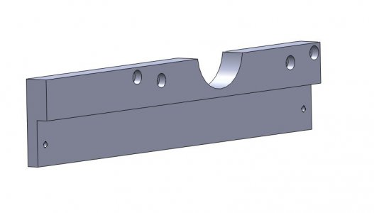
I have do two DRO installs with glass scales. One was an old mill/drill and the other was a Grizzly G0755mill/drill. I mounted the Y scale to a 3/4" thick bar attached to the saddle under the table. I had to provide clearance for the X axis lead screw bearing housing but otherwise not a problem. The counterbored holes mount to tapped holes in the saddle. Additional threaded holes were used in the bar for mounting a scale cover. If needed, an access hole for the gib adjustment can be added.Went to recheck that my read head would indeed cover the gib adjustment screws and discovered that what I thought were the gib adjustment screws actually were the screws that held the half nut in place for the y axis lead screw. What a rookie! So mounting the scale at the rear should not be a problem.
Brooks: moving on to the Y axis it appears that your P-M machine has a vertical surface that you were able to mount your Y axis scale to, is that correct? My machine has the base sloped at about 60 degrees.
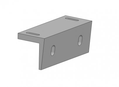
I have seen magnetic scales mounted on the sloped base of a machine like mine but the glass scales I have are much larger top to bottom, and more sensitive to chips. To mount the scales vertically will mean they will have to stand off quite a ways from the sloped base, which would mean a long bent arm to go over the scale and down to the moving read head. Right now I am thinking of machining a long wedge to go on the sloped base which would give a vertical surface to mount the scale to. Since the wedge would be mounted to the cast base I assume shimming would be necessary. Or perhaps there is a better or easier way.
Dennis


I did a DRO Install on my G0704
Photo's Here!
