- Joined
- Jul 28, 2017
- Messages
- 2,390
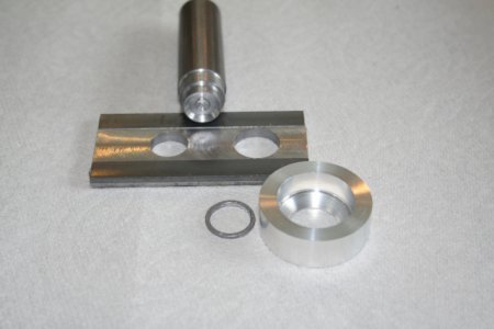
As part of the by-now gargantuan "needing more than a spark test" thread that a few of us have been involved with, I needed to make a lead ring to prevent our x-ray detector from being directly exposed to our x-ray sources (Americium-241 used in smoke detectors). The OD and ID are unique, dependent on the source/detector geometry so I decided to make a punch and die for it. This is the first time I've done such a thing and it was a fun little project. Here's a photo of the punch and die, a ring I made using it, and the part of my XRF hardware the ring is supposed to mate with. It will fit in the bottom of the aluminum piece. The aluminum piece will be used to aim the x-ray sources toward the sample.

The punch has two sections, a smaller-diameter end that defines the ID and a larger-diameter section that defines the OD. The die has two bored-out holes to match the punch. I made both from HRS because lead is very soft. To make a ring, a small lead sheet is placed over the smaller-diameter hole in the die and the punch is used to make the ID. The 1/16" thick lead sheet is not removed from the punch. Then the punch is moved over to the larger hole and the finished ring is punched out. I know the exact spacing between the two holes so it's easy to get the proper alignment between the punch and die.
The end of the punch has a conical profile to provide a little bit of relief and concentrate force on the perimeter of the disk being punched out. I used the same small-nose-radius TCMT style insert to cut a relief for the OD portion of the punch as well. I used a very fine-tooth file while spinning the punch on my lathe to remove the burrs so the punch slid smoothly into the die, and that also gave me a cleaner cut.
I also used my 1.25" carbide insert mill to level the top of the die where the holes were bored. That was done _before_ boring the holes so the holes didn't perturb the cutting action of the end mill.
I used my benchtop mill as the "arbor press" for punching out the ring.

