- Joined
- Jun 17, 2011
- Messages
- 2,062
I was doing a bit of research on VFDs this morning when I found this site: https://www.pumpsandsystems.com/preventing-drive-induced-electrical-damage-ac-motor-bearings
They're talking about voltages being induced in the shaft of a motor being run from a VFD. I recall from my training as an electrician that different frequencies of AC require different 'amounts' of iron and copper to accomplish the same tasks. For example, AC systems on aircraft may run at 400 Hz, rather than 60 Hz, because the transformers and other inductive equipment can be made smaller and lighter.
The site was pointing out that voltages up to 70 VAC can be induced in the shafts of motors when powered by VFDs. I got curious and measured the voltage between the output shaft of the motor on my RF-30 and it's mount. When it was running, I measured up to 2.4 VAC at around 44 Hz. The readings were lower at other frequencies and lowest at 60 Hz. On my big lathe (2 HP motor) the highest reading was just over 3 VAC at 10 Hz, and decreasing as the frequency rose.
Any on this forum who have played with EDM (Electrical Discharge Machining) know that we use fairly low DC voltages to remove bits of metal. For that matter, arc welders operate at relatively low AC or DC voltages. The point of the site is that the races on the bearings can be damaged over time when running at various frequencies.
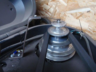
Just to be sure, and because I needed something to do to stay out of our current heat wave, I made up a couple of wipers to provide a path to ground , bypassing the bearings on my motors.
I had a bag of flat springs I got at Restore, so I used those for the contacts. The ball bearing further reduces wear. The yellow wire connects to the motor mount.

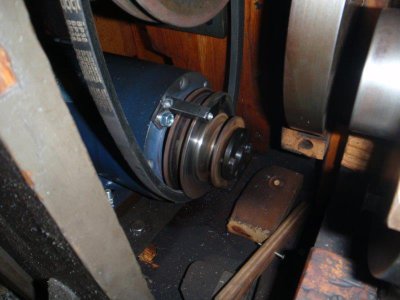
On the lathe, I had to sand off some rust from the side of the pulley, to improve the contact. You have to look closely to see the strap spring.

I don't know if this will make the slightest difference in the long run. I just thought it was interesting, and it did fill the need for something to do in the cool of the shop.
They're talking about voltages being induced in the shaft of a motor being run from a VFD. I recall from my training as an electrician that different frequencies of AC require different 'amounts' of iron and copper to accomplish the same tasks. For example, AC systems on aircraft may run at 400 Hz, rather than 60 Hz, because the transformers and other inductive equipment can be made smaller and lighter.
The site was pointing out that voltages up to 70 VAC can be induced in the shafts of motors when powered by VFDs. I got curious and measured the voltage between the output shaft of the motor on my RF-30 and it's mount. When it was running, I measured up to 2.4 VAC at around 44 Hz. The readings were lower at other frequencies and lowest at 60 Hz. On my big lathe (2 HP motor) the highest reading was just over 3 VAC at 10 Hz, and decreasing as the frequency rose.
Any on this forum who have played with EDM (Electrical Discharge Machining) know that we use fairly low DC voltages to remove bits of metal. For that matter, arc welders operate at relatively low AC or DC voltages. The point of the site is that the races on the bearings can be damaged over time when running at various frequencies.
Just to be sure, and because I needed something to do to stay out of our current heat wave, I made up a couple of wipers to provide a path to ground , bypassing the bearings on my motors.
I had a bag of flat springs I got at Restore, so I used those for the contacts. The ball bearing further reduces wear. The yellow wire connects to the motor mount.

On the lathe, I had to sand off some rust from the side of the pulley, to improve the contact. You have to look closely to see the strap spring.

I don't know if this will make the slightest difference in the long run. I just thought it was interesting, and it did fill the need for something to do in the cool of the shop.


