Please Help mw with a Huanyang VFD

Al Slitter

Active User
Registered
Joined
Jul 26, 2014
Messages
93
Hello All;
I purchased a used lathe and it came with a 3-HP 3-Phase motor. I live in Thailand and the power here is 220 Volt 50Hz.
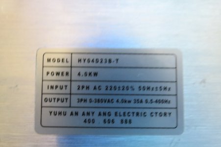
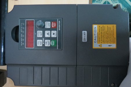
The motor had been set up to run 380 Volts 3-Phase and try as I could I could not find anyone here to switch the motor back to 220 Volts 3-Phase as the plate from the motor was missing. So what I had to do was to Purchase a VFD that was capable of taking in 220 Volts AC and then changing it to 380 volts 3-Phase. I checked with several people and I was advise to purchase this model Huanyang GT Series Inverter Model #HY04D23B-T.
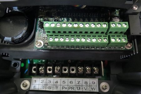
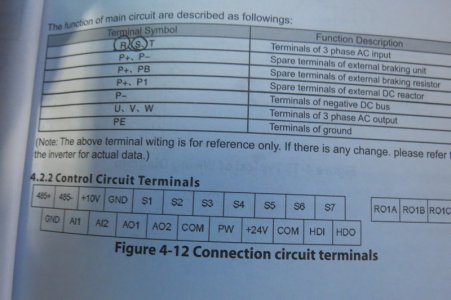
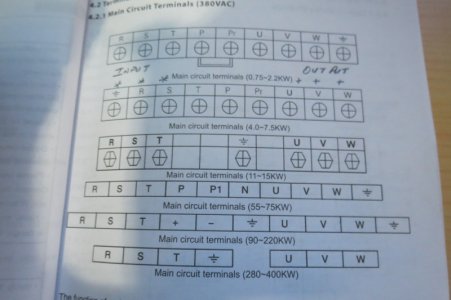
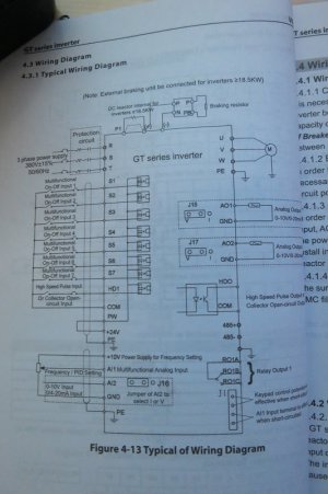
I have now wired up the inverter to the lathe and have tried to set up the parameters so the unit will run in its basic mode by using the front panel of the VFD. However I cannot get the unit to start the motor as something is wrong or most likely I have not set up the VFD correctly. I am including information on the motor as well as images I took from the VFD and the user’s manual.
If someone could please walk me through the set up slowly it would be greatly appreciated.
My Motor:
The motor is a Mitsubishi Superline motor and is listed as being from Japan, I think.
It says: Three Phase Induction Motor.
3HP 4 Pole Type SB-E
JIS C 4004 Frame 100L
Hertz 50 Rotor C
Voltage 220/ 380 Ins. Class E
AMP 8.7 / 5.0 Rating Con
RPM 1420 Amb. Temp 40Degrees C
Code H
Weight 28Kg.
Bearing 6206ZZ & 3205ZZ

Here are images of the VFD and Manual that I hope might help you in getting me started?

IMG_1534.JPG

IMG_1537.JPG

IMG_1532.JPG

IMG_1538.JPG

IMG_1539.JPG

IMG_1540.JPG

I will be happy to provide any other information that you might require to get this unit running!

Best Regards

Al

IMG_1534.JPG IMG_1537.JPG IMG_1532.JPG IMG_1538.JPG IMG_1539.JPG IMG_1540.JPG
 
if you have the input power on terminals R and S then a ground on terminal E
and the output to the intended motor on U,V,W and then a ground wire to E, that's where you want to start.
you will have to set the parameters of operation next.
 
I have the very same 3HP unit. I know the manual makes you feel upside down a tad! Been there... Did that (a lot) - Do you plan to wire this into any existing frwd/ and rev. controls later? Any Interlocks and obvious safegaurds via limits you may need to input to the VFD to stop the motor? Jim D. had a really good post recently on this w/ a Schematic and lots of good info. Search the Forum for VFD lathe and Dawson.....

As for your Codes - I think I have mine all written down in the book. Do you have a list of the ones you changed or set? Let me know if you want me to post back my codes. When you power up the unit, what do you get on the display initially? And then you press RUN and what happens?
 
if you have the input power on terminals R and S then a ground on terminal E
and the output to the intended motor on U,V,W and then a ground wire to E, that's where you want to start.
you will have to set the parameters of operation next.

Yes have configured the VFD that way and the unit is running!
 
I have the very same 3HP unit. I know the manual makes you feel upside down a tad! Been there... Did that (a lot) - Do you plan to wire this into any existing frwd/ and rev. controls later? Any Interlocks and obvious safegaurds via limits you may need to input to the VFD to stop the motor? Jim D. had a really good post recently on this w/ a Schematic and lots of good info. Search the Forum for VFD lathe and Dawson.....

As for your Codes - I think I have mine all written down in the book. Do you have a list of the ones you changed or set? Let me know if you want me to post back my codes. When you power up the unit, what do you get on the display initially? And then you press RUN and what happens?

Thank you for the quick reply and assurance that others have been in the situation that I am in, this is driving me crazy and my wife is all over me for not getting the lathe working after spending so much money on it.
Regarding your question about what I want to set up when complete, I want only to configure a remote On/Off switch on the lathe.
The lathe has good speed control and reversing capabilities already so I want to keep this conversion very simple. I hope you follow my thinking.
The codes that I have changed or confirmed are as follows:
P2.01 (Power) ???
P2.02 (Frequency) 50 Hz.
P2.03 (Speed) 1420 RPM
P2.04 (Voltage) 380 Volts
P2.05 (Current) 5 Amps

I do not know the following:
P2.06 Motor Stator Resistance ?
P2.07 Motor Rotor Resistance ?
P2.08 Motor Stator and Rotor inductance ?
P2.09 Motor Stator and Rotor mutual inductance ?
P2.010 Motor current without load ?

I am not sure what is meant by the Note:
The motor should be de-coupled from the load; otherwise the parameters obtained by auto tune may be incorrect.

Regarding the settings P0.02
P0.03
P0.04
P0.05
P0.06
P0.07
P0.08 etc.
I am not sure what I put in I did my best based on what I know and what I thought the manual was saying!

Thank you


Al
 
I have the very same 3HP unit. I know the manual makes you feel upside down a tad! Been there... Did that (a lot) - Do you plan to wire this into any existing frwd/ and rev. controls later? Any Interlocks and obvious safegaurds via limits you may need to input to the VFD to stop the motor? Jim D. had a really good post recently on this w/ a Schematic and lots of good info. Search the Forum for VFD lathe and Dawson.....

As for your Codes - I think I have mine all written down in the book. Do you have a list of the ones you changed or set? Let me know if you want me to post back my codes. When you power up the unit, what do you get on the display initially? And then you press RUN and what happens?

I forgot to add;
I tried a search for VFD lathe and Dawson on this site and came up empty!
I would appreciate any codes that you might have that would work for me.
I want to keep this install simple at the beginning with all of the control on the VFD, later I will attempt to wire in a remote On/Off switch!

Regards

Al
 
[FONT=&amp]I am not aware of current VFDs being able to generate a voltage higher than their input voltage. The diagram you show, shows 380V 3 phase in to get adjustable 380V 3 phase out, but the manual is pretty generic. I could not find any information listed for this model[/FONT]. I believe based on the nameplate nomenclature the correct model number is HY04D023B. The B-T might be some new step-up converter version, but I would contact the seller as to how this is done/programmed. It could be your set-up parameters are wrong, or source of the run commands are not correct. I have not used this brand of VFDs, but here are some programing parameters you might review below. See if you can get it running first (even on lower output voltage), then we can fine tune the parameters. I would also read the manual for other VFDs, they often give a better description of the parameters and effect.

Model~ HY 04D0 23 B
Inverter Capacity, 04D0 means 4KW
Voltage Rating, 23 means 1-phase 220V
Software Version B
There is nothing related to your model number in the manual, but all the ones listed with the 23 in their model number are Single & Three Phase 220V 50Hz. All the ones listed with 43 in their model number are 3Φ380V 50Hz

Code​
Function​
Set Range & Function Explanation
Factory Setting​
PD001​
Source of Run Commands 0:Operator
1:External terminal
2:Communication port
0
0= front panel
1=External switch controls via Multi-Input 1-6
PD002​
Source of Operating Frequency​
0:Operator
1:External terminal
2:Communication port
0
0=front panel
1= speed 10K potentiometer via terminals VR, VI, ACM
PD003​
Main Frequency 0.00~400.00 Hz
0.00​
Unclear, other set this to max. Operating freq. Try 50Hz
PD004​
Base Frequency 0.01~400.00 Hz
50.00​
Motor name plate frequency usually 50 or 60 Hz; so 50Hz
PD005​
Max Operating Frequency 50.00~400.00 Hz
50.00​
Allows one to overdrive the motor speed. Usually 1.5x base freq. So if a higher operating RPM is needed, consider 60 or 75Hz. This also allows more adjustment range in any one gear. So you might use a range of 30-75Hz on the lathe. This is fine for most 3 phase motors.
PD006​
Intermediate Frequency 0.01~400.00 Hz
2.50/3.0​
Usually transition freq. for other functions.
PD007​
Min. Frequency 0.01~20.00 Hz
0.50​
Cut off freq, or lowest freq motor can operate at. You can set the lower cutoff freq of the VFD with PD011. This is a factor for preventing motors running at very low speeds they are not rated for. Might set it to 2 or 5 Hz if motor is not inverter rated.
PD008​
Max. Voltage 0.1V—*
220/380​
Assume this would be 380V for your motor
PD141​
Rated Motor Voltage Set according to Motor nameplate
-​
In this case would 380V for your motor, some motors are dual voltage, so could be different then 008 setting.
PD142​
Rated Motor Current Set according to Motor nameplate
-​
5A per your information
PD143​
Motor pole number. Set according to Motor nameplate
04​
04 for ~1450/1750RPM (50/60Hz) motor
PD144​
Rated Motor Revolution Nameplate base speed
1440​
~1450/1750RPM (50/60Hz) motor with 4 poles
 
I also searched and am not able to locate my post.

Here is what I think the settings should be.

PD001 0
PD002 0
PD003 0
PD004 50

PD006 3.0

PD008 380
PD009 27.5
PD010 13.5

PD014 10.0 (just a good starting point)
PD015 10.0

PD025 0

With the motor parameters set correctly, this should get your running.

I hope this helps.
 
[FONT=&amp]I am not aware of current VFDs being able to generate a voltage higher than their input voltage. The diagram you show, shows 380V 3 phase in to get adjustable 380V 3 phase out, but the manual is pretty generic. I could not find any information listed for this model[/FONT]. I believe based on the nameplate nomenclature the correct model number is HY04D023B. The B-T might be some new step-up converter version, but I would contact the seller as to how this is done/programmed. It could be your set-up parameters are wrong, or source of the run commands are not correct. I have not used this brand of VFDs, but here are some programing parameters you might review below. See if you can get it running first (even on lower output voltage), then we can fine tune the parameters. I would also read the manual for other VFDs, they often give a better description of the parameters and effect.

Model~ HY 04D0 23 B
Inverter Capacity, 04D0 means 4KW
Voltage Rating, 23 means 1-phase 220V
Software Version B
There is nothing related to your model number in the manual, but all the ones listed with the 23 in their model number are Single & Three Phase 220V 50Hz. All the ones listed with 43 in their model number are 3Φ380V 50Hz

Code​
Function​
Set Range & Function Explanation
Factory Setting​
PD001​
Source of Run Commands 0:Operator
1:External terminal
2:Communication port
0 0= front panel
1=External switch controls via Multi-Input 1-6
PD002​
Source of Operating Frequency​
0:Operator
1:External terminal
2:Communication port
0 0=front panel
1= speed 10K potentiometer via terminals VR, VI, ACM
PD003​
Main Frequency 0.00~400.00 Hz
0.00​
Unclear, other set this to max. Operating freq. Try 50Hz
PD004​
Base Frequency 0.01~400.00 Hz
50.00​
Motor name plate frequency usually 50 or 60 Hz; so 50Hz
PD005​
Max Operating Frequency 50.00~400.00 Hz
50.00​
Allows one to overdrive the motor speed. Usually 1.5x base freq. So if a higher operating RPM is needed, consider 60 or 75Hz. This also allows more adjustment range in any one gear. So you might use a range of 30-75Hz on the lathe. This is fine for most 3 phase motors.
PD006​
Intermediate Frequency 0.01~400.00 Hz
2.50/3.0​
Usually transition freq. for other functions.
PD007​
Min. Frequency 0.01~20.00 Hz
0.50​
Cut off freq, or lowest freq motor can operate at. You can set the lower cutoff freq of the VFD with PD011. This is a factor for preventing motors running at very low speeds they are not rated for. Might set it to 2 or 5 Hz if motor is not inverter rated.
PD008​
Max. Voltage 0.1V—*
220/380​
Assume this would be 380V for your motor
PD141​
Rated Motor Voltage Set according to Motor nameplate
-​
In this case would 380V for your motor, some motors are dual voltage, so could be different then 008 setting.
PD142​
Rated Motor Current Set according to Motor nameplate
-​
5A per your information
PD143​
Motor pole number. Set according to Motor nameplate
04​
04 for ~1450/1750RPM (50/60Hz) motor
PD144​
Rated Motor Revolution Nameplate base speed
1440​
~1450/1750RPM (50/60Hz) motor with 4 poles

I understand what you are saying about the Input voltage equaling the output voltage, it was for this reason that I had to pay a lot more money for a unit that is supposed to do that!
Here is a link to the site and specifications:
http://www.aliexpress.com/item/5HP-...-VFD-Inverter-Phase-Converter/1445497658.html

I will contact the agent who I bought it from and try and get additional information from them, however I am concerned about there knowledge level.

Regards

Al
Hello, I could find no where in my manual or in the software in the VFD any way of selecting a PDxxx function.
My system uses codes such as P0.xxx, P1.xxx, P2.0xxx, P3.0xxx etc.

Very confusing and frustrating especially after spending that amount of money!

Regards

Al
 
Back
Top