- Joined
- Jan 16, 2020
- Messages
- 8
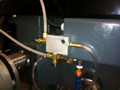
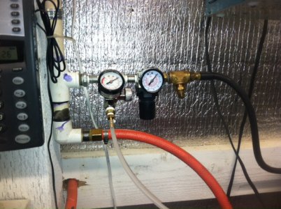
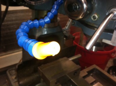
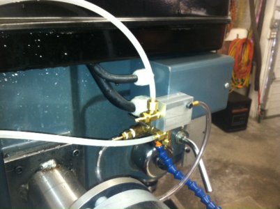
The plans listed below are for building your own no fog coolant system to use in your shop. Compressed air is required, but the design will apply coolant to your cutting tools without creating a foggy mist in the air when it is used properly. In practice, the air volume is turned up just enough to gently blow chips away from the cutting area, which will also carry small droplets of coolant to the tool.
Most dimensions can be changed without issue, however there are two dimensions that are critical: the .040" hole in the mixing block, and the .040" hole in the nozzle. The air passage through the mixing block must be large enough to slow the speed of the air flowing through it, but must be small enough for the air to travel fast enough to carry the droplets of coolant along.
I made my mixing block from brass for three reasons, but aluminum could be used: 1. I like the look of brass 2. It was what I had 3. Allows assembly by soldering if desired
The drawings show using only one regulator on the system, but two can be used, providing different pressure settings for the mixer air and for the fluid reservoir.
This coolant system could be used with any light coolant, such as Kool Mist, WD-40, or even soluble oil. Heavy cutting oils will most likely not work well with this system.
The drawings and bill of materials depict the system as I am currently building mine. If it becomes necessary to make changes to a drawing, I will do so and post the revised drawing here, replacing the original, then will post a note to the thread. As always, some individuals will do some things differently, and that is okay.
Comments and ideas are welcome, let me know what you think.
View attachment NO_FOG_MISTER_001.pdf - Coolant system overview
View attachment NO_FOG_MISTER_002.pdf - Regulator and air fittings
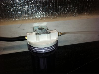
View attachment NO_FOG_MISTER_003.pdf - Reservoir and fittings
View attachment NO_FOG_MISTER_004.pdf - Reservoir modification details
View attachment NO_FOG_MISTER_005.pdf - Mixer head assembly
View attachment NO_FOG_MISTER_006.pdf - Mixer component details in English/Imperial measurements
View attachment NO_FOG_MISTER_006M.pdf - Mixer component details in Metric measurements
View attachment NO_FOG_MISTER_007.pdf - Bill of materials
ON EDIT: I discovered an error on one of the drawings regarding the nozzle size, and it has been increased from .040" to .090" and it works much better at this size. Alternatively, the nozzle could be eliminated and the coolant could exit directly from the extension tube.
All drawings have been updated as of 1/11/2015
Last edited by a moderator:

