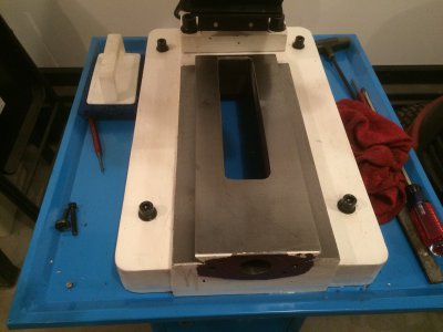
New PM25MV on the way!

If i can find a mobile rack that is cheap enough, i sure will rack mount it. I'd like to do that with the pc too, so it's all in one unit. I'd get one big enough for a second control panel also, for a future cnc lathe. The cnc control box is a 4u height for rack mounting.
 
Not much wiring done today, been fighting with the final fit of the enclosure most of the day. none of the side plate screw holes line up. In addition to that, the back panel is about 1/16 inch too long on one side, so it didn't fit between the side plates. Yes i could have milled it down, probably faster, but it was late, and i opted to do it with a large double cut bastard file. After about 20 minutes of filing, voila, back plate now fits.
On the side plates, i ended up putting the top and bottom on then drilling larger holes and using the socket screws with nuts on the inside. Seemed to be the only way to get every thing lined up properly.
After that, got the 110v circuits all wired up, will post pics of it tomorrow. Have to wire up the rest of it now, then I have to wait for the final parts to get here on Wednesday or Thursday before i can test.
 
This really can be a problem especially with the crisp dry colder months approaching. It is always a good idea to discharge immediately (grab the ground strap for example) when walking up to your table. Also, avoid static producing clothing like sweaters and nylon jackets. A company I used to work for required test line workers to wear conductive smocks after a person in packaging (wearing a ground strap) was zapping microprocessor oscillators.

-Joe

Please do be careful of static discharge. If you were doing this in one of my labs with no ESD protection we would have to have a chat. ;) (joke)

If nothing else, there are these little adapters that plug into a standard 3-prong outlet to bring out the ground so a wrist strap can be attached. Just don't want you popping something while having all this fun. :)
 
How goes the assembly? I am playing with my machine, but I really do not know what I am doing, so no finished product yet.
 
The ball screws are supposed to be here tomorrow, but the rest of the control panel parts won't be here until saturday or monday. I'm at a standstill on the control box until i get them. I will probably do the machine cleaning and disassembly this weekend to prep for ball screw installation. Not sure how i'm going to do the clearance on the saddle, as i don't have a drill press, but i'll figure out something. I may have to take it in to work to do it after hours.
Meanwhile, still having major issues with the cam software, that i'm trying to get worked through. For the money it cost, i do think it should have worked considerably better than it has. I'm thinking i would have been better off just programming with the g-code directly. I'll get it resolved one way or another, whether they provide me with a download that actually works, or i get my money back.
 
Sorry to hear about the software troubles. Cleaning the machine up is not too bad I have not taken my head off yet as I have been using the mill to fab up some brackets for my DRO install. I have been making the job overly complicated, but I guess that is the fun of it. My leadscrews were packed with black gunk that I had to scrub out with a stiff bristle brush. the table moves like butter now all the way out to the end.
 
Got some new pics today, so here goes!
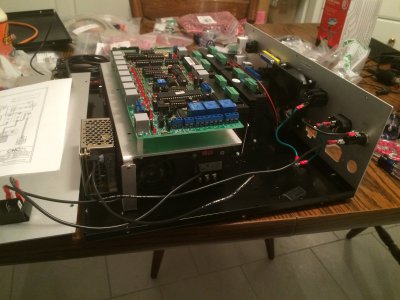
We will start with some control box wiring pictures. Bear in mind that i will go back after i make sure everything works and tidy up the wires, but for now, just connecting everything.

Wiring up the chassis ground.
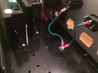
001.JPG

Working on the 110v circuit.
002.JPG

110v circuit complete with both power supplies, and the auxiliary 110v plug for coolant pump.
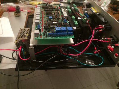
003.JPG

These are replacing some items that came in the kit. The ethernet connectors on the right are rubberized panel mount pass through connectors with a pigtail. These replace 3 of the way too long ethernet patchcords that came in the kit. the 4 red ethernet cables will be to connect the drivers, again to replace the way too long cables that came in the kit. the black ethernet cable is for the external e-stop/probe board connector, once again to replace the way too long cable.
the new cables are 1ft long, vs the 3ft cables that came with the kit. These came from MCM Electronics, and were very reasonable on price. the 1ft cables were less than 2 bucks each.
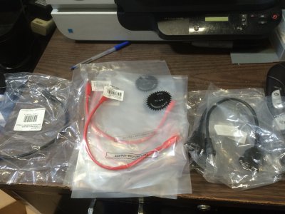
004.JPG

Here are the motor cable connectors soldered up that connect to the drivers. Red is A+ on pin 1, white is A- on pin 2, Black is B+ on pin 3, and green is B- on pin 4. I'm not the best at soldering, but they are done and holding. The wires are 18awg, in SO 18/4 cord form, i replaced the hookup wire in the kit with this, will keep things more neat and tidy.
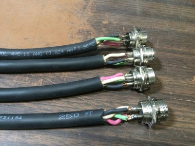
006.JPG

001.JPG 002.JPG 003.JPG 004.JPG 006.JPG
 
Last edited:
Mechanical pictures in this post.

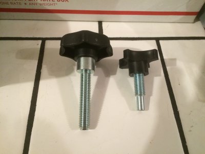
The new knob on the left for the mobile base to replace the way too short knob that came with it on the right. These came from McMaster-Carr.
007.JPG

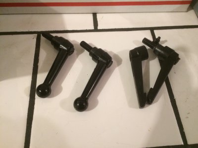
the new far more durable adjustable handles are on the left, and the way-to-easily broken ones that came with the mill are on the right. Again, these came from McMaster-Carr.
008.JPG

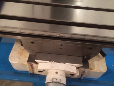
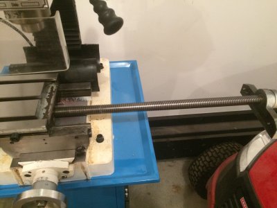
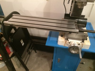
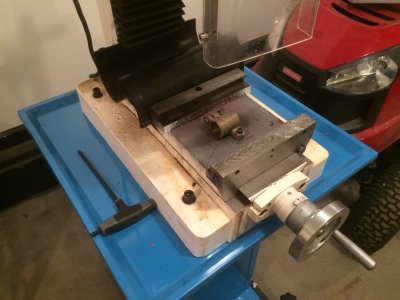
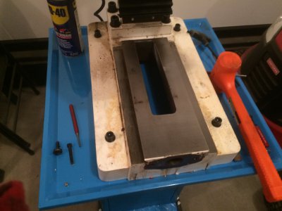
Starting dis-assembly of the table for cleaning and ball screw installation.
009.JPG

010.JPG

011.JPG

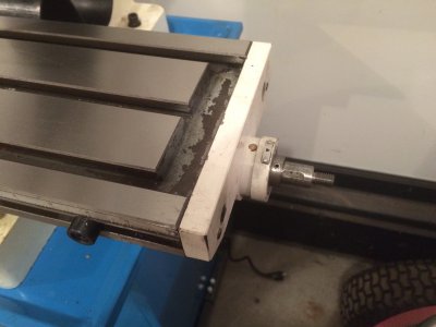
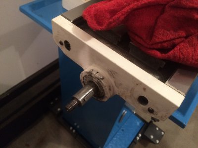
Removing the x-axis screw
012.JPG

007.JPG 008.JPG 009.JPG 010.JPG 011.JPG 012.JPG
 
More mechanical pics.

Table about ready to be removed. I have already removed the gib at this point.
013.JPG

Table removed.
015.JPG

Saddle removed.
016.JPG

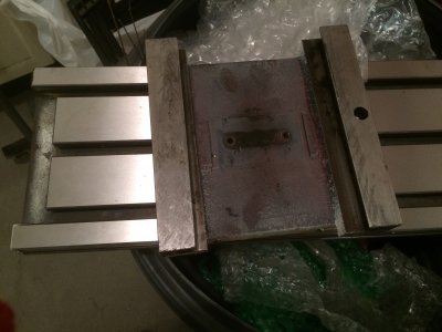
In this pic of the saddle, you can see where i am going to have to machine slots and clearance the saddle for the ball screw mounts and nuts. It's a pretty rough casting at this point.
In addition, my mounting kit for the ball srews is actually for the G0704, the table motor mount and end plates have bolt holes in slightly different locations than the PM25MV does, so i am going to have to slot the motor mount and end plate to adapt to this mill. The G0704 bolt holes and pin locations are higher up on the end of the table than the PM25MV.
017.JPG

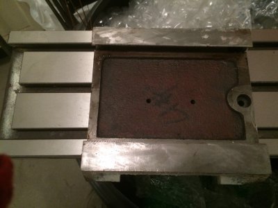
bottom side of the table casting.
018.JPG

Base all cleaned up, this is it for pics today. :allgood:
019.JPG

Before i install the ball screws, i may lap the y-axis on the saddle to make sure it's smooth all the way to the end, and do the same with the x-axis and the table.

013.JPG 015.JPG 016.JPG 017.JPG 018.JPG 019.JPG
 
i was just checking Grizzly's website, a whole saddle is only 80 bucks, i may just buy that casting and see if i can adapt it to the PM25MV, and if it works, will save me a ton of extra work milling ball screw slots and tapping holes. If it doesn't work, i can always use it for something else down the road.

Couple reasons this would be awesome if it fits.

1. I don't have access to a mill or a drill press while this machine is torn down.
2. Since to get the slots machined on the current saddle, i'll have to pay the local machine shop to do it, if the grizzly saddle fits, will save me a ton of cash there vs just 80 for a saddle with the slots already in it, and, i can put this machine back together long enough to mill the clearance pocket in the grizzly saddle, then swap them out and install the ball screws.
3. This would also enable me to be able to mill the lubrication slots in the saddle for an oiling system with the original machine put back together before the ball screw installation.
 
Last edited:
Back
Top